Digital Twin of a Cobot
My contribution in the AVATAR project has been to develop the digital twin of a cobot, aimed at its implementation in a more complex virtual scene simulating a production process environment.
First of all, cobots are particular types of robots meant to collaborate with human operators during the performance of particular tasks. The impact of cobots is so impressive in the automatization of the manufacturing process that it has become the fastest growing segment of the global industrial robotics market.
As it will be explained later more in detail, I have started from the choice of a cobot basing on the use case (pick and place of the catenaccio component). After this, I have passed through different softwares according to the operation to be performed. As all the participants to the project, I have carried out my work as a part of two different groups. In my specific case, during the whole semester I have collaborated above all with the students of my university for the development of a specific use case. Each of the group focused on different parts and so I have dedicated to the cobot, that is supposed to carry out some operations in an automatized way, thus allowing an upgrade in terms of production.
In the final part of the semester instead, I was part of the group of students that, like me, worked on cobots and on their cinematic model. This gave us the possibility to compare the different methods with which it is possible to face the same problem, to discuss the pros and cons of such methods and also to give and receive feedbacks. Despite each of us inevitably proceeded in its own way, it has been possible, obviously, to outline some common traits in the work so to define a workflow for the development of the digital twin of a cobot.
Poster
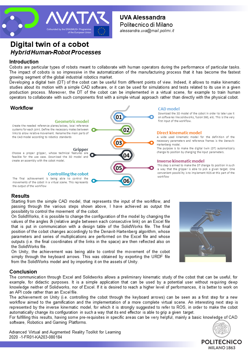
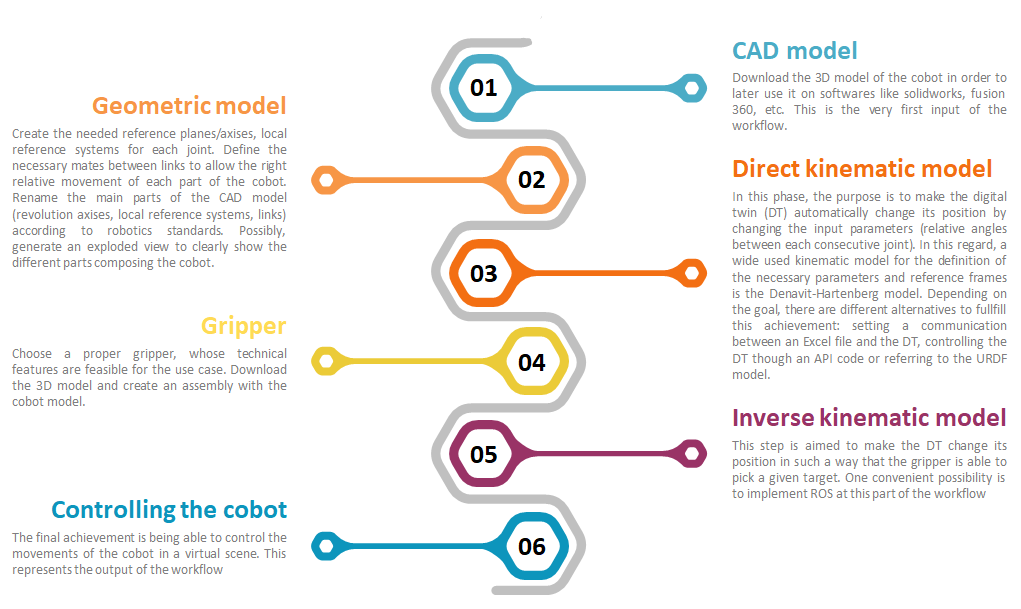
Workflow development
| INPUTS: Cobot manufacturing task to be performed | 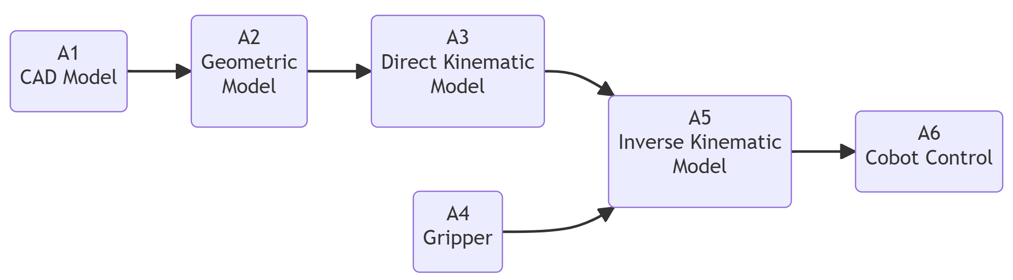 | OUTPUTS: Robot Control |
Workflow building-blocks
| Acitivities | Overview |
|---|---|
| A1 CAD Model | • Description: First of all, the catalog of 6-dof cobots offered by Universal Robot was consulted. For the choice of the best solution for our use case, starting of course from defining the operations that the cobot is supposed to perform. In figure 1 there is the CAD model of the part with which the cobot will interact when performing the simple task of pick and place objects. In particular, it is supposed to pick the catenaccio component and place it on the plate (whereas the assembly catenaccio+plate will be positioned on the thombstone by the human operator). By making calculation the weight of the catenaccio component results to be less than 5 kg. In figure 2 the 5 cobot models offered by Universal Robotsand are shown and it is possible to understand that the best solution is the ur5e cobot that is able to support a payload of maximum 5 kg. Then, the 3D cad model (.stp format) was downloaded from the website and opened in solidworks. • Input: Robotic manufacturing task to be performed • Output: CAD Model of the cobot • Control: Cobot technical information • Resource : Cobot manufacturer or supplier and Solidworks |
| A2 Geometric Model | • Description: - Download the 3D CAD model from the website (.stp format) - Open the step file on Solidworks - Select the first component on the feature manager (the one father of all the other components), right-click and select “Dissolve Feature”. - Save the model as an assembly (.SLDASM format). Now you are able to make changes on the model. - On the feature manager, re-arrange the hierarchy and re-name the components according to the robotics standards like shown in the picture. In order to make a part children of another, use the “Form New Subassembly”.! 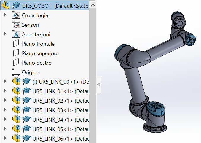 - Set all the links as mobile, except for the base one (UR5_LINK_00), that is fixed. - Define the mates (tangent surfaces/coaxial surfaces) for allowing the relative movements between each link. - Create an exploded view and, possibly, create an animation of it. This is not an indispensable step, but it could be useful for making clear the different parts composing the cobot. • Input: CAD Model • Output: Structured CAD Asemsembly • Control: Solidworks, interference Detection, assembly verification • Resource : Solidworks |
| A3 Direct Kinematic Model | • Description: In order to study the kinematic model of the cobot, the documentation provided by the UR website about the Denavit-Hartenberg model applied to the specific case of their cobots. According to the scheme of the DH parameters given in the documentation, on solidworks it is necessary to define the local reference systems of each joint as shown below: 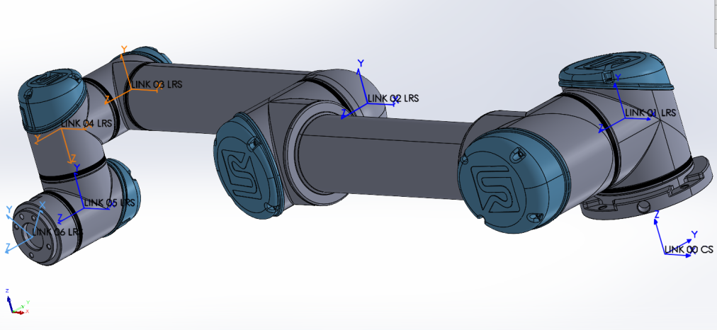 In the link for the UR documentation provided above, it is possible to find an attached excel file named DH-Transformation.xlsx. By opening the excel file, there is first of all a table with the four DH parameters defined for each joint, that represent the input data for the series of multiplication of matrices performed in the rest of the excel file. Such operations allow to compute the final coordinates of each joint, thus defining the final configuration of the cobot in the space and on the excel file it is given also a graphical representation of it, in particular the xy plane (top view), xz plane and yz plane (lateral views). But on these graphs it is represented just a rough scheme of the cobot and it is difficult to picture in mind how it is positioned in the 3D space. In order to have a clearer visualization of the cobot in the space, I tried to control through this excel file also the cobot model on solidworks, so that by changing the values on the excel file, also the cobot model moves accordingly. This is at the purpose of easily studying the preliminary aspects of the kinematics of the cobot through the communication of excel and a cad software like solidworks. In order to achieve this, the best way resulted to define first of all the relative angles between one joint and the previous one. Angles include θ1 (angle between link 1 and the base link), θ2 (relative angle between link 2 and link 1), and so forth. 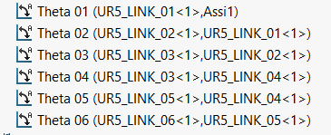 The next step is to create a table on solidworks with these angle parameters and to connect each cell of this table with the corresponding cell on the previous excel file. 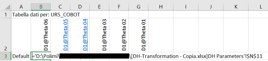 By doing so, the result is that by changing the values of the angles on the excel file, the values are automatically updated also on the design table on solidworks by simply opening it. Then, by closing the table, the cobot model changes its position according to the new input values. Regardint the set of input θ angles reported in the table below (the other parameters are constant), the resultant configuration of the cobot in the space is the one shown in the other picure. 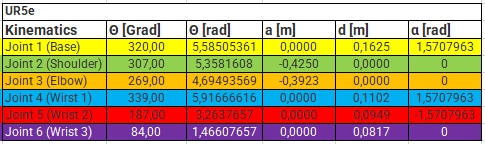 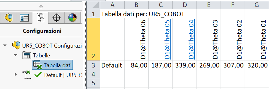 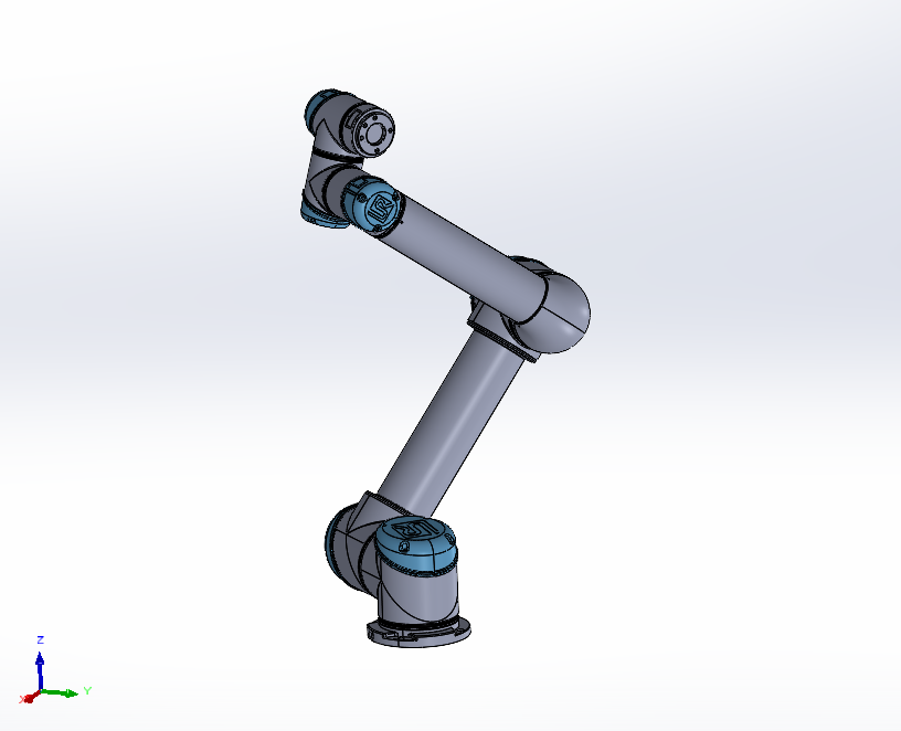 Moreover, by comparing each view of the graphs on the Excel file with the corresponding one on solidworks, it is possible to see that effectively the configuration of the cobot coincides as a proof that the communication works. 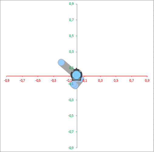 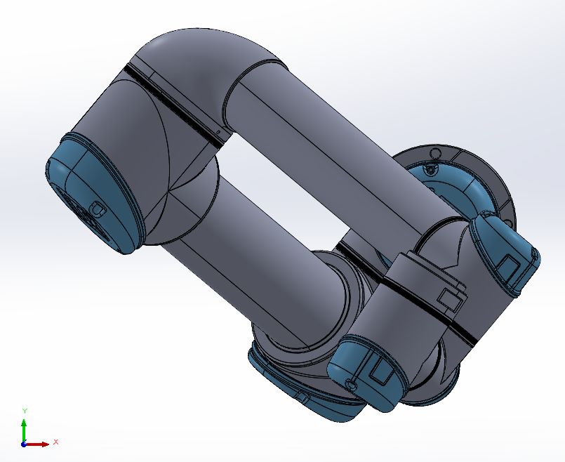 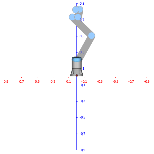 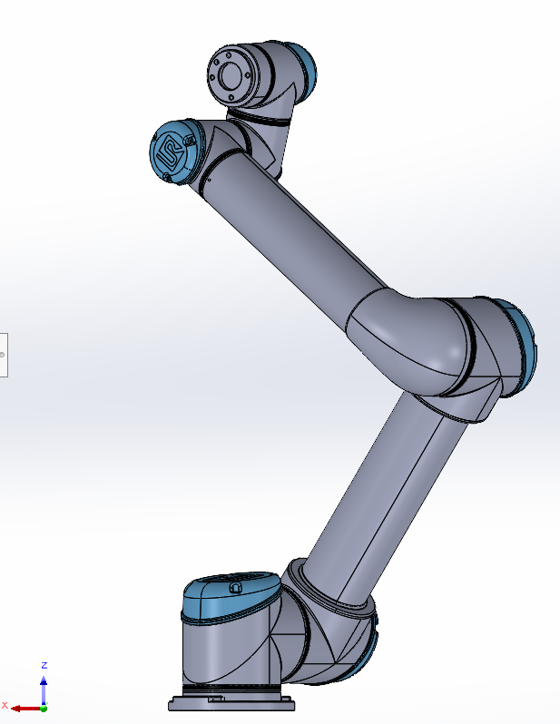 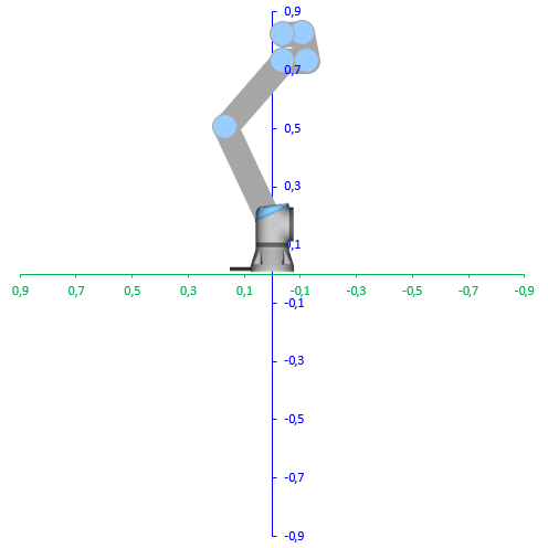 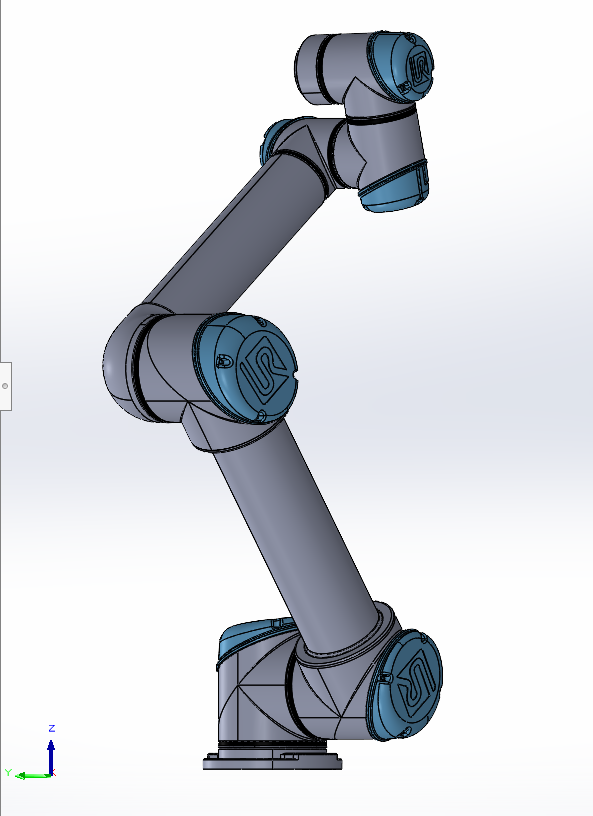 It is possible now to highlight some pros and cons about this communication between Excel and SolidWorks. Among the advantages: - It allows an easy 3D view of the cobot position, according to the Denavit Hartenberg model - For a potential user, for example a student, it is an easy application, not requiring deep knowledge of the softwares (neither Solidworks, nor Excel) - Preliminary kinematic study of the cobot through a simple CAD software. The latter advantage can be seen also as also a drawback in the sense that it is not possible to go into a deeper analysis with this tool. Another disadvantage is that the communication is quite time consuming because if the values on the Excel table are changed, then the cobot on solidworks doesn’t move directly but it is needed to first open the deisgn table so that the values of the angles are updated and only after closing that, the cobot changes position. In case it is required to increase the performance of the direct kinematic study it is better to work on an API code or referring to the URDF model. • Input: Solidworks Assembly, DH-Transformation.xlsx • Output: Manual control, cobot pose visualization 2D (Excel) and 3D (Solidworks) • Control: Cobot pose accuracy • Resource : Solidworks, Excel, DH parameters |
| A4 Gripper | • Description: A suggestion to be done for the choice of the gripper is to prefer a parallel model, because it is characterized by a simple geometry that does not bring complications for the later work on Unity 3D. Considered that, the 2FG7 model of the OnRobot company, that is compatible with the UR5e cobot and whose technical details, reported in the following table, make it adapt for the transfer of the catenaccio component. 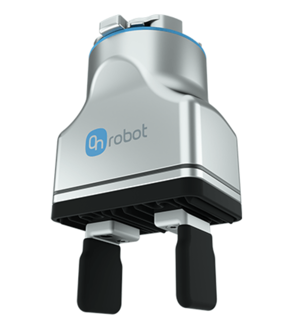 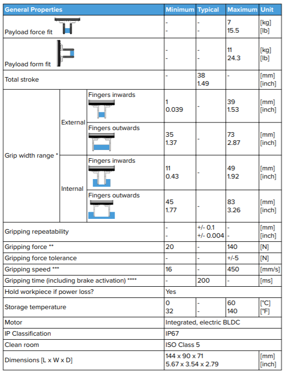 After having downloaded the .stp file, I have opened it on Solidworks repeating some steps explained in the paragraph related to the CAD model and then I have integrated it to the cobot assembly, as shown in the pictures below. 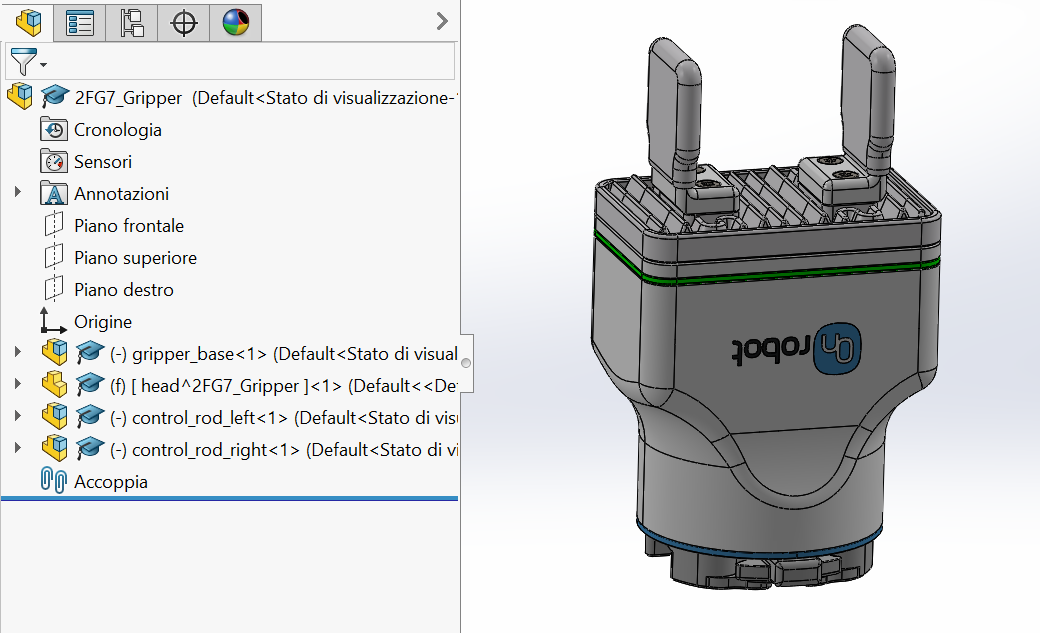 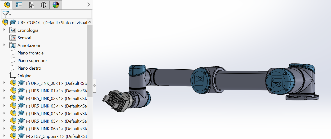 • Input: Solidworks Assembly, Gripper .step file • Output: Cobot + End Effector • Control: Assembly definition • Resource : SolidWorks, Gripper manufacturer |
| A5 Inverse Kinematic Model | • Description: The study of the inverse kinematic model is aimed to make the cobot automatically change its position in such a way that its end effector is able to reach and grip a given target. This is an important step of the workflow that has been mainly developed by other students from the project but not by me, this is why I am only mentioning it. • Input: Cobot in Solidworks • Output: Cobot’s Inverse Kinematics • Control: Corret pose solution for given target • Resource : SolidWorks |
| A6 Robot Control | • Description: This final phase is aimed to achieve the ability of controlling the cobot in a virtual scene, by importing it in a gaming platform like Unity 3D. At this puporse, it referred to the URDF (Unified Robot Description Format) model that is a SolidWorks add-in that allows for the export of SW Parts and Assemblies into a URDF file URDF Exporter. Through this tool, it havr to create a new tree hierarchy, where the base link is fix as the parent of link1, link1 parent of link2 and so. Then, after some step, the exporter creates a ROS-like package that contains a directory for meshes, textures and robots (urdf files). Input: Solidworks Assembly, URDF Exporter • Output: URDF Package for simulation • Control: Successful reading of the package in ROS • Resource : SolidWorks, URDF Exporter and ROS |
Conclusion
During the semester, we had the possibility to explore different softwares, so that this allowed us to be able to decide which software fits better for a given application and to achieve the results shown up to now, for what concern my work. For fulfilling this, having some pre-requisites in specific areas can be very helpful, mainly a basic knowledge of CAD software, Robotics and Gaming Platforms. The final achievement on Unity (i.e. controlling the cobot through the keyboard arrows) can be seen as a first step for a new workflow aimed to the gamification and the implementation of a more complete virtual scene, that can include the various machines and objects involved in a real production process. An interesting next step is represented by the inverse kinematic model, for which it is strongly suggested to refer to ROS, in order to make the cobot automatically change its configuration in such a way that its end effector is able to grip a given target.
Avatar for me
Avatar for me has represented a chance to actively explore the tools related to the Industry 4.0 in an international context, of which I have really appreciated the possibility to exchange knowledge both with professors and students from different countries.