Manufacturing Environment for a Machining Center and Pallet Assembly
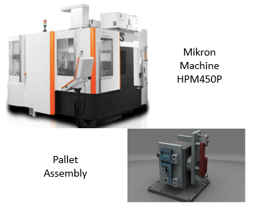
The purpose of this document is to offer a comprehensive set of guidelines that can be used for the creation of a Virtual Reality scene of 3D CAD models. These models represent the input of the following workflow and should be provided in some neutral format in order to be able to go through all the steps of the workflow. The output, instead, is a VR scene that can be easily accessed through a completely web-based solution. In the following, the workflow description is particularly referred to these assets reported in the figure.
Poster
Workflow development
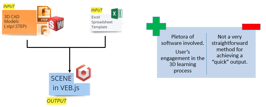
| INPUT: CAD Models | 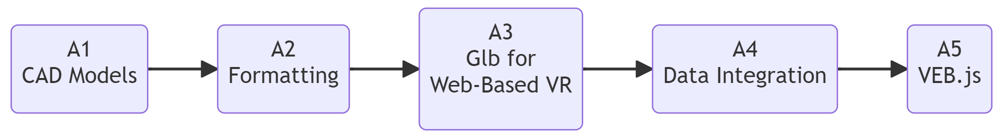 | OUTPUT: VEB.js - Virtual Environment based on Babylon.js |
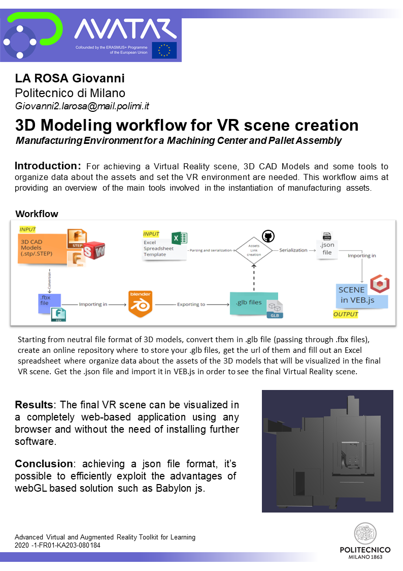
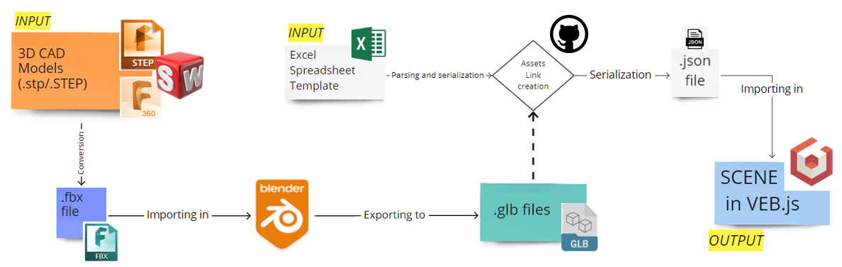
Before starting, here in the figure a brief description of the workflow designed in order to get a final Virtual Reality scene starting from 3D CAD Models. Here the main steps, software, tools and file formats involved in this workflow are highlighted.
Workflow building-blocks
| Acitivities | Overview |
|---|---|
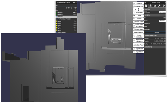
| A1 CAD Models | • Description: Among the inputs this workflow starts from, there are .STEP or .stp models and, in particular, the ones of the Mikron Machine HPM450U and the Pallet Assembly. Opening them in SolidWorks or Fusion360, you should see something similar to what is reported in this following figure. 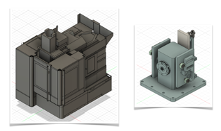 We decided to use mainly Fusion360 to open these models and get familiar with them. Among the activities performed at this stage: 1. Check of the existing hierarchy of parts inside the models 2. Hierarchy redefinition 3. Renaming of most important parts of the new hierarchy. For the Mikron Machine HPM450U, the discriminant in the renaming activity is the distinction between static and dynamic parts the machine is made of and, as an example, in the following you can see a figure of the new parts’ names given adopting this method. Here you can see in red the dynamics parts (which may be parents of some static children parts) and, in green, the main static part that reprsents the structure of the machine itself. 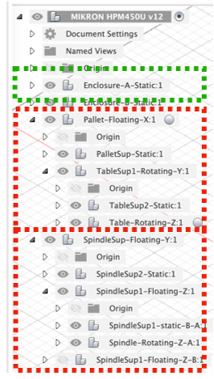 Of course, to understand which parts are static and which are dynamic, it is good to study the documentation provided and understand the motion dynamics and statics of the system. Pretty much the same is done for the Pallet Assembly, but actually, here, since it is about fixtures, the approach was different and the hierarchy redefinition comes with mainly the distinction between workpieces and base plates. The 3D model of the pallet is basically made of 3 workpieces that actually represent the different states of an object (the raw piece, the Work In Progress 1 and the Work In Progress 2). This means that this 3D model represents also the sequence of operations performed on a particular object. It can be useful to define also children parts each pallet’s part is made of as explained later when the second input (the Excel spreadsheet) is presented. The next figure provides a quick overview of the pallet’s parts of interest. 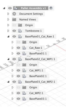 As you may understand, having less components to deal with, can speed up the next animation workflow and can make easier the identification of components that actually can move or can be moved inside the virtual reality environment. • Input: CAD models in STEP or .stp files, (Mikron Machine HPM450U and the Pallet Assembly) • Output: Redefinition of the hierarchy with the identification between static and dynamic • Control: Study of the motion dynamics and statics of the system from the documentation provided and the system itself • Resource: CAD software (e.g., SolidWorks, Fusion360), .STEP or .stp models of the machinery, system documentation |
| A2 Formatting | • Description: The second step of this workflow is about the creation of the .fbx files. FBX stands for FilmBox and it is a format used to exchange 3D geometry and animation data. This kind of files are used in augmented and virtual reality development. Fusion360 supports the creation of the .fbx files starting from STEP or stp files. • Input: .STEP or .stp files • Output: .fbx files for XR enviroments • Control: In Blender, checking scale of the models, axes, origins of the parts, relative positions, etc • Resource: Blender |
| A3 Glb for Web-Based VR | • Description: Starting from the .fbx file, the third step is to import them in Blender. Blender is the free and open-source 3D creation suite. It supports the entirety of the 3D pipeline—modeling, rigging, animation, simulation, rendering, compositing and motion tracking, even video editing and game creation. Among the files that can be opened by this software, there are .fbx, .obj, .stl and so on. Among these, .fbx format is a much more advanced format that can hold much more data with respect to .OBJ format which only keeps geometry as .stl format too. 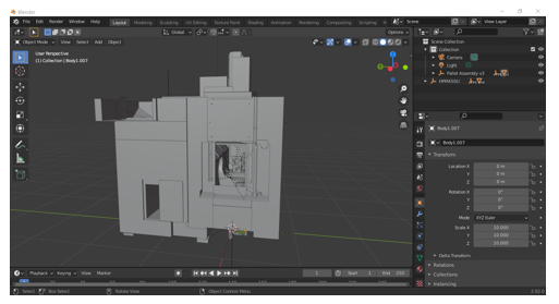 In Blender you can check the scale of the models, the axes, the origins of the parts, the relative positions and so on, but let’s say that the final activity performed within the purposes of this workflow is the exporting to the .glb file. This kind of file format is the binary version of the glTF file format and it is defined as the «JPEG of 3D». • Input: .fbx files • Output: .glb files for Web-Based VR • Control: Cobot pose accuracy • Resource: Solidworks, Excel, DH parameters |
| A4 Data Integration | • Description: The fourth step is made of 2 main activities: 1. Download of the Excel spreadsheet and subsequent compilation of it 2. From .glb files to link creation exploiting online repositories It’s time for the second main input, the Excel spreadsheet. Basically, it is a simple .xls file made of 2 sheets, the first defines the «context» and the second sheet «Assets» is about the definition of these assets inside the scene. In this sheet, the previously identified assets parts’ names are put in the column «id», and other data, such as the «inScene», «type» (which defines the type of assets identified for example by an OWL class) and so on, must or should be filled out. Here in the following picture, some ids relative to the specific use cases is provided. Check also the names of the Pallet Assembly’s hierarchy that, here, have to be shown. 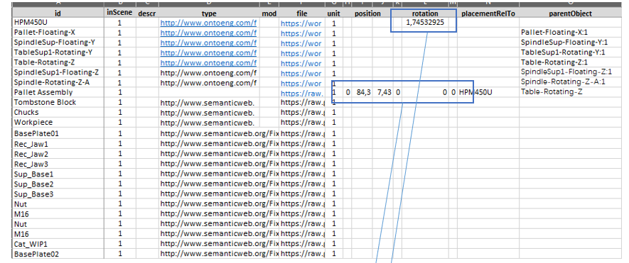 An important information to insert in this Excel file is the file path of the 3D models. This column works with the https domain and in order to get this, a decision could be to get the file path from an online repository in GitHub. Basically, you can create an account, create a project and a dedicated repository. Uploading .glb files there, you are able to get each file path and put it inside the spreadsheet. The link is the same for all the parts within a .glb file, so, in order to specify the correspondent part, you can put an # after the link and the “id” of the specific part after it. In the specific Excel cell, under the column “file”, you can put something like that: https://github.com/GiovanniLaRosa/AVATAR-Public/blob/main/02.MikronMachineHPM450U.glb#Pallet-Floating-X 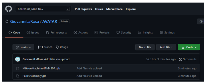 Among the other information that you need to provide in order to properly fill the Excel spreadsheet, there are the “position” and “rotation” data that are particularly important if you are going to represent more assets exploiting this methodology. Indeed, you need to define the relative position and rotation that assets have with respect to each other. A quick parenthesis on the way the excel spreadsheet should be compiled is needed, in particular when you will deal with the column named «type». Here you are requested to go, for example, through ontologies. >Ontologies are frameworks for representing sharable and reusable knowledge across a domain. >The ontologies’ ability to describe relationships and their high interconnectedness make them the bases for modeling high-quality, linked and coherent data. In this use case, fixture ontologies for pallet’s parts are considered. To open ontologies you need some ontologies editor such as Protégé. As you can see from the screen, the “Classes” can provide you interesting information about the current nomenclature of parts belonging to a specific domain. 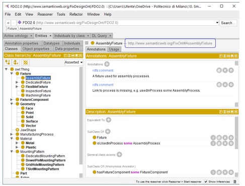 Inside the Excel Spreadsheet, there is a specific toolkit which allows you to get the final .json file. As you may know, JSON stands for JavaScript Object Notation and it is very widely used for transmitting data in web applications. In the case of interest, the first part of the json file gotten by the Excel spreadsheet is as this screen suggests. 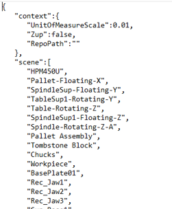 • Input: Excel spreadsheet, .glb files, ontologies, online server like GitHub repository • Output: Compiled Excel spreadsheet with defined asset attributes and a .json file with data in web applications • Control: Ontology relationships • Resource: Excel software, ontology editor (e.g., Protégé), GitHub or similar online hosting, .json file |
| A5 VEB.js | • Description: The last step, for this workflow, was to import this file in VEB.js that is the Virtual Environment based on Babylon.js. You can check this link for more information, but, basically, VEB.js is a reconfigurable model-driven virtual environment application and you can open it using its functionalities as the following picture shows. 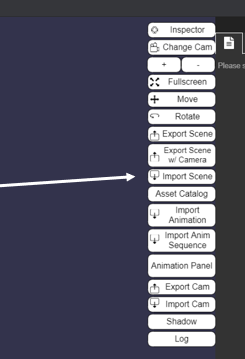 • Input: .json file • Output: VEB.js virtual environment • Control: Importing the .json file into VEB.js • Resource: VEB.js, Babylon.js, for importing and handling .json file data |
Results
Finally, importing the scene and so the final aggregated .json file, you are able to upload your assets. Everything is now ready for making some animations. The animation can be performed using the potentialities of the JSON format but this is out the scope of this workflow.
By the way, it should be underlined, that the final reached output is just the input of other further workflows that can be done also in terms of animation of the loaded 3D scene. Following the entire designed workflow, you should be able to see the something similar to what you have in the next figure.
Why to get a scene within VEB.js?
The main reasons identified during the design of this workflow are reported in the following:
- Compared with other software, like modeling software such as Blender, SolidWorks, or also game engine like Unity 3D, Babylon.js is based on HTML5 and OpenGL. This means that you can load your virtual scene inside any browser and this represents an important flexibility aspect
- It’s even easier to share and distribute virtual scene with anyone, you will need just a link and some JSON file in online repositories.
- It’s a webGL based solution and so there is not the need to install heavy software and platforms on your computer, moreover, you can see the scene also in other devices since you need just an internet connection to load scenes
- Last but not the least, it’s completely open source and you don’t need any license to use it.
Of course, there are some drawbacks such as the fact that you have less features compared to the other installed software and the more full of assets the final scene is, the more time your browser could take to load the scene and visualize it correctly.
Conclusion
The designed workflow starts from existing 3D CAD models, a simple Excel template (that works as a notebook for the assets organization) and ends with the creation of the scene using Babylon.js. In order to obtain this output a lot of tools and software were used. Of course, this workflow can be improved and it’s not perfect because it achieves a result that maybe can be achieved in less time using a smaller number of software, tools and file formats.
However, it offers a broader view on a plethora of different software and file formats that can allow a user to experiment with different methods and become familiar with them. Therefore, it can be used not only to create an object, that is the final Virtual Reality scene, but also to learn more about the different tools, understand their functions and main uses.
Finally, one of the most important thing is to understand that Virtual Reality is a graphical interface that supports the broader digital twin concept. Indeed, the final output of each Virtual Reality scene creation should be the link between physical and digital twin thanks to a graphical interface provided by some tools such as Babylon.js itself.
Avatar for me
It was a long journey, full of team activities and high level lectures. XR technologies are becoming more and more important nowadays. At the beginning, I found these technologies quite new and the lectures helped me in better familiarizing with them. Dropped in manufacturing activities, Virtual Reality and Augmented Reality become even more important helping practitioners in the decision making process, for example when simulating a machinig process before realizing it physically. Since the beginning I was involved in the creation of a Virtual Reality scene starting from existing 3D CAD models, understanding, then, how to make them animate and how to build an entire virtual factory. My activities for this case study were focalized on the experimentation of different tools and several file formats. I discovered that a lot of tools are available on the web and that most of them are open source applications. This will make easier their usage in the next future. At the beginning of the project the principal milestones were to understand more about the topic and to share the new acquired knowledge by providing tutorials and formalizing workflows. I think that we achieved these goals with a lot of efforts and commitments, so, let’s hope that, during the next years, this work can be beneficial for new brilliant students.