A1.2 - Assembly Generation
For the purpose of this workflow, when approaching the re-modeling of industrial equipment and products in terms of parts and assemblies, a crucial aspect to consider for the instatiation of factory assets is the identification of elementary components in the objects’ hierarchies; For this task, it is not relevant to refer to the actual, real-world bill of materials of a given object and the related assembly structure; considering the requirements of the target application for these assets, that is the implementation inside a virtual environment, a simpler identification method can be based on the distinction between static and floating components, to be appropriately grouped as multibody parts if they are constituted by subcomponents that are jointly connected as in the case of the vibrating bowl presented in A1 (all static). Furthermore, the positions of the origins as defined in A1 must be used to characterize more complex assemblies by specifying the relative position of subcomponents according to the following steps:
- Multiparts assets will have a parent empty object to which its static components will be referenced and positioned.
- Subcomponents have to be grouped matching the hierarchy of the assembly, i.e., assets forming a sub-assembly must be grouped together.
- Parenthood relationships between the 3D models have to be defined by specifying the associate relative positioning. CAD environments use this approach to manage multipart assemblies and dependencies.
The example below shows a pin insertion station in which static and floating components are treted as hierarchy nodes. For example, the tip of the insertion machine is indicated with the “Floating_X” suffix (“X” stands for the direction of the movement relative to the workstation’s system of reference; “Y” and “Z” can also be found in other configurations or for other machines) so that it can be displaced (i.e., its positional data are set to vary across a series of timestamps) relative to its parent, which does not change its position when animations are launched and is indicated by the “Static” suffix. Other parts that do not have any related child and don’t move are indicated only by their name and do not have the “Static/Floating” suffix (e.g, “Conveyor Main”, “Vibrating Bowl Pins”). Additional details on this case can be found here.
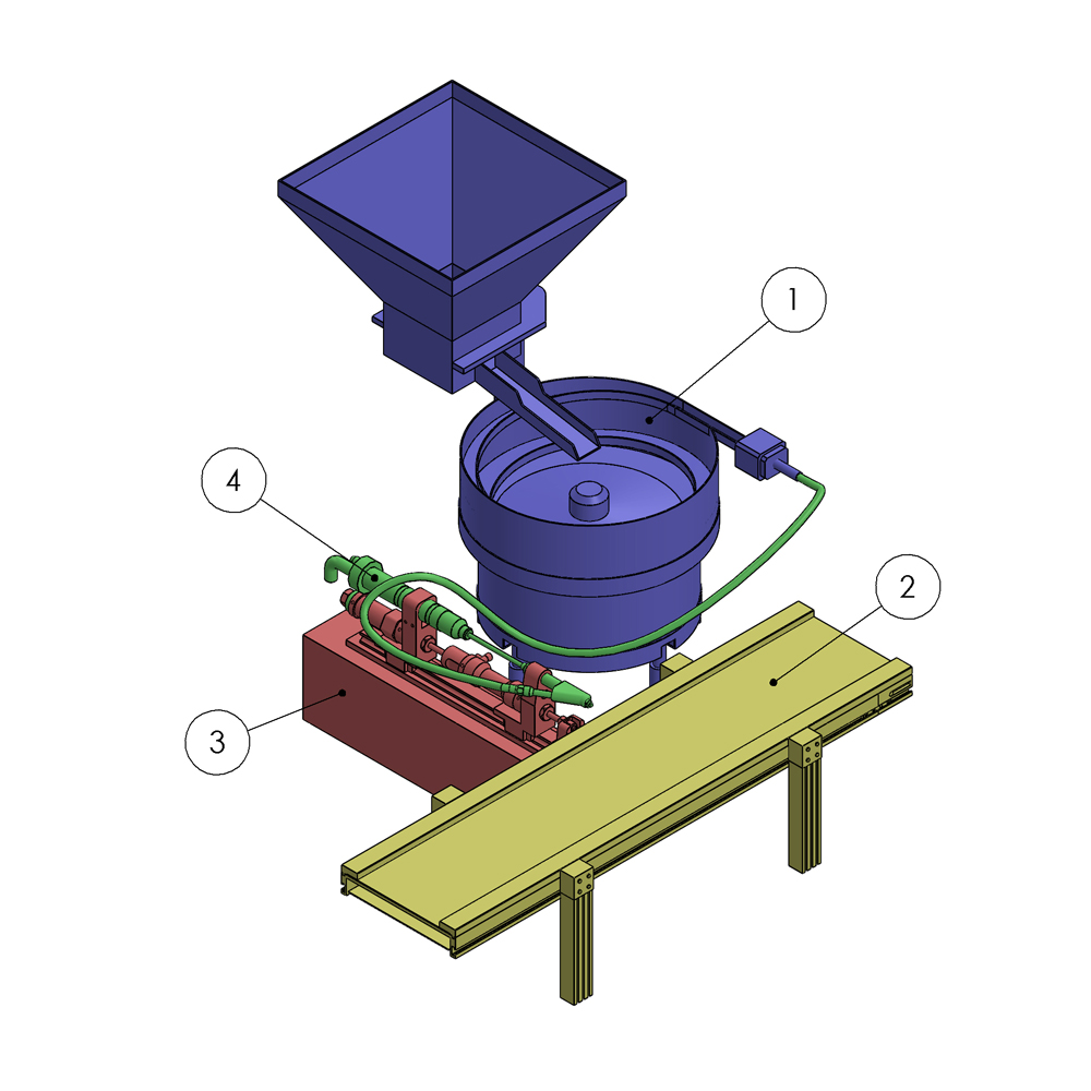
Pin insertion station with ballons
| Component ID | Label | Parent | Relative Position [mm] |
|---|---|---|---|
| Vibrating_Bowl | 1 | Pin Insertion_Station | [-633.24, 0,-335.51] |
| Conveyor | 2 | Pin Insertion_Station | 0, 0, 0 |
| PI_Machine_Static | 3 | Pin Insertion_Station | [-417.5, 0, 0] |
| PI_Machine_FloatingX | 4 | PI_Machine_Static | [21, 146.59, -218.71] |
A similar approach has been applied to another case previously developed in the context of the AVATAR project, available here.
At this point, assemblies can be created according to two - equally valid - approaches:
- Bottom-up: single parts of elementary components are joint in a higher level assembly.
- Top-down: a complex part or assembly model is split into elementary objects according to a given instatiation method (i.e., static/floating components). This is usually the case of assets downloaded from the web (i.e., models of collaborative robots), whose hierarchies should be manually recreated.
Input
Industrial system or equipment CAD models needing to be re-modeled for virtual reality.
Output
Remodeled CAD model of a system or industrial equipment for use in a virtual environment, broken down into elementary components with a defined parent-child relationship along with relative positions of the children and their parents.
Control
Management of assembly inheritance along with the distinction and categorization of static and floating components. Accurate definition of the relative positions of components in more complex assemblies.
Resources
- CAD Software: SOLIDWORKS, CREO, CATIA, NX, etc.
- Modeling Softwares
- Hierarchical structure of the assembly