COBOZ - Cobot Training from VR
This project aims to leverage the potential of Virtual Reality (VR) and Digital Twin (DT) technologies to enhance academic or industrial training experiences. The immersive features of VR, coupled with the advanced capabilities of DT technologies, empower the creation of a 3D virtual environment that simulates potentially dangerous or remote environments. Taking a Cobot as a case study, our project wants to ensure that users understand the basic principles of how cobots operate in a safe virtual environment. This encompasses critical areas such as safety, accuracy, ergonomics and seamless human-robot collaboration, the project has two main objectives:
- VR training for Cobot operation:
Using VR for training allows new Cobot operators to gain experience in a risk-free environment, ensuring effective real-world collaboration.
- Standardized framework for developing VR training:
This will provide a basis for creating VR training modules for other machinery, such as 3D printers, improving safety and efficiency across multiple industrial tools.
VR training for Cobot operation
The first part of this project is to implement a training program in the VR environment to educate potential users of a Cobot. These potential users could be a worker in industry or a student in school or university. This virtual reality environment should include all the elements present in the physical environment in order to guarantee a better immersion and an experience as close as possible to reality. In order to meet this requirement. Additionally, the user should be able to execute a ‘Pick and Place’ operation with the robot, mirroring the experience of interacting with the actual machine.
The scene is composed by:
- Cobot UR16e
- Control unit
- Control Tablet
- Table for the Cobor
- The virtual interface
- Pick and place components
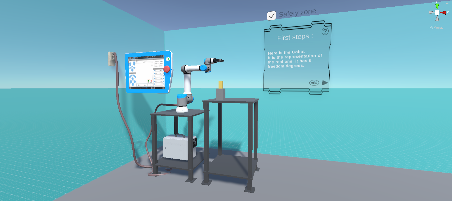
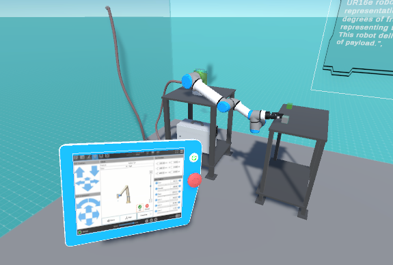
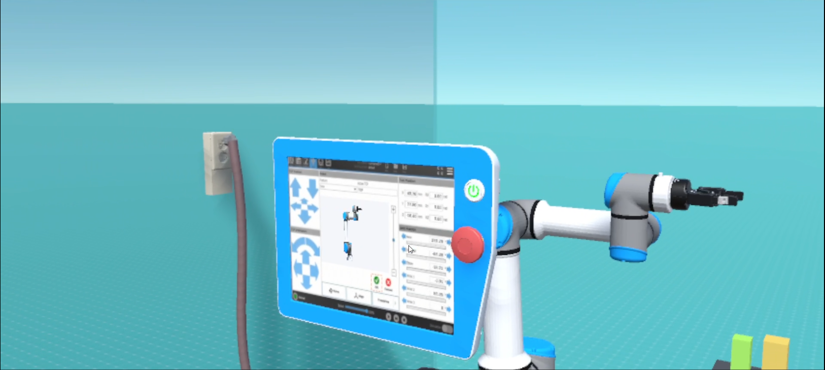
Virtual Environment Scene
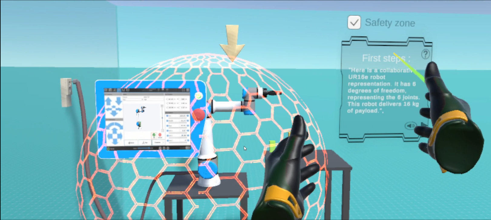
After having modeled the environment, the environment had to be interactive. It must give information and indications to the user for each element in the environment. To do this, the environment communicates with the user by means of pop-ups that display information and directions to the user, as well as arrows and highlights. For a complete immersion the user can not only read the information but also listen to it.
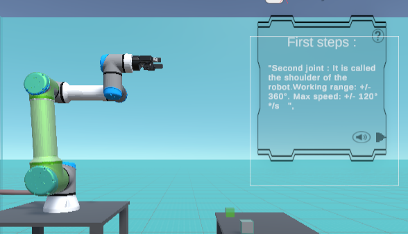
Information about the highlighted joint
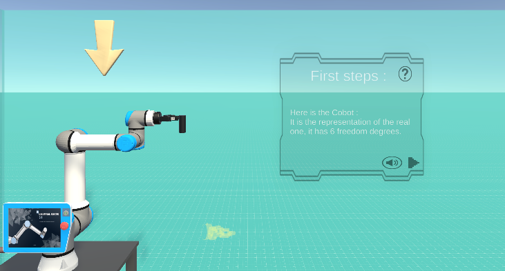
Pop-up with an arrow showing the cobot
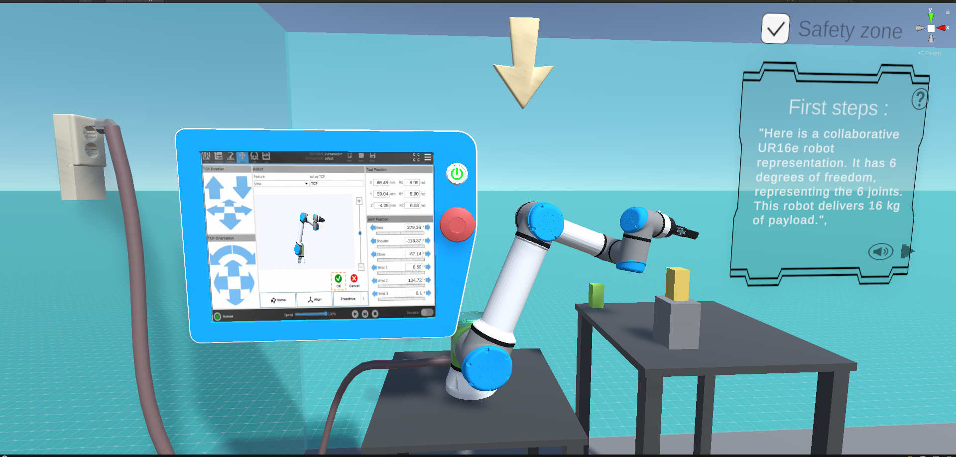
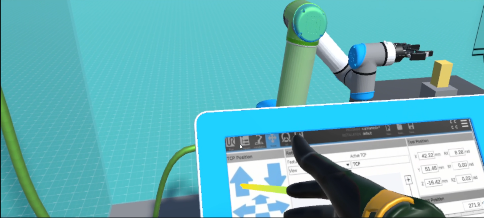
After having received all the indications and information concerning the cobot. The user must be able to move the cobot in the environment, to pick up objects and also to move them. To do this, the user has a tablet in the virtual environment that is identical to the real tablet.
With this tablet the user can not only move the cobot tool which results in the relative movement of the joints (inverse kinematics) but also move each joint at his convenience.
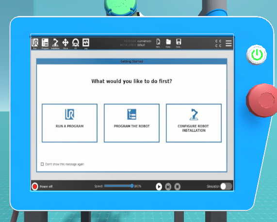
Tablet interface
Moving the cobot using the tablet
VR Expirience
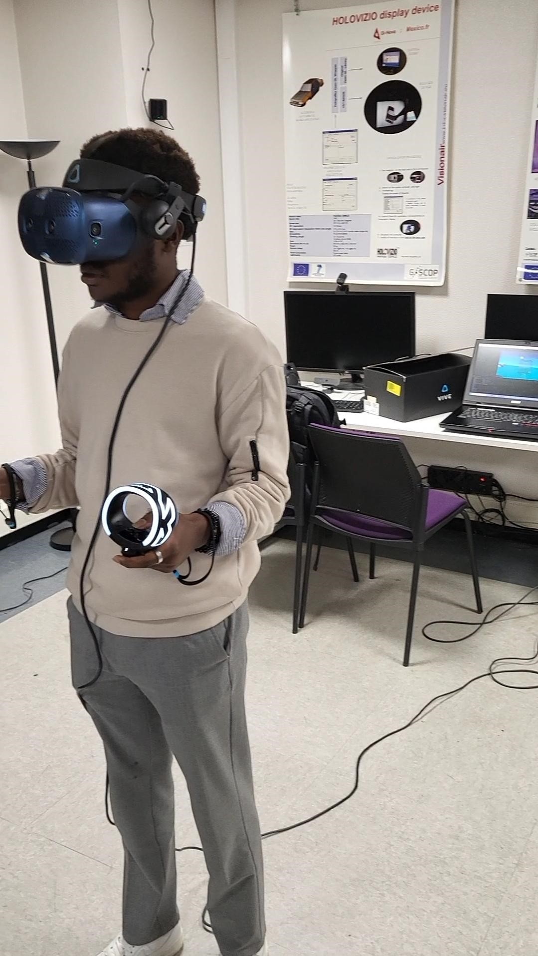
user using the virtual tablet
- Discovering the enviroment
- Interactions
Standardized framework for developing VR training
The making of a Training application on VR follows many steps, this elaboration could be complex and tricky, this workflow aims to somehow standardize and lead to a logical plan to implement such an application, steps are defined according to a methodological pattern represented with the diagram below:
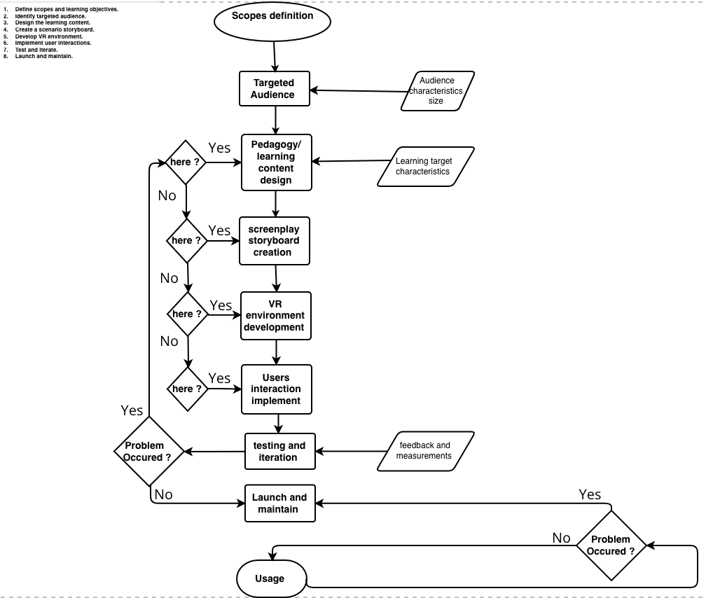
Main workflow diagram, how to do a training session on VR
This process diagram describe the sequencing steps followed to implement such an application, each step is described as follows :
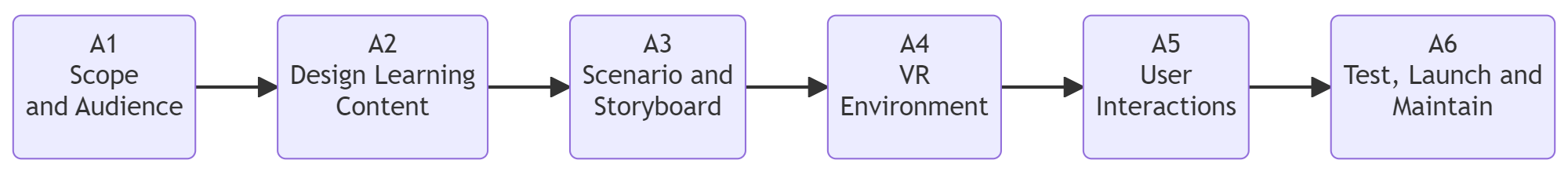
Main workflow and the activities
Workflow Description
| Acitivities | Overview |
|---|---|
| A1 Scope and Audience | • Description: First, determine learning goals. Defining expectations from VR program. What will this training teach the user to accomplish? This phase is about needs and requirement. Also, the intended users of VR application should be identified. Because different users will need different approaches, designs, and indicators. This stage permits planning material and user experience. • Input: Preliminary idea or concept of the VR program and any pre-existing training or educational materials that can serve as a basis for the VR program. • Output: Clearly defined learning objectives and expectations for the VR program through identification of expected user groups and their specific needs. • Control: Periodic meetings for review and validation with stakeholders to ensure that the learning objectives are in line with their expectations. • Resource: Periodic meetings for review and validation with stakeholders to ensure that the learning objectives are in line with their expectations. |
| A2 Design Learning content | • Description: Create educational tools and resources for virtual reality that offer a richer experience than traditional media via interactive scenarios, dynamic simulations and immersive exercises. • Input: Feedback and opinions from users and stakeholders on desired VR experiences. Technical specifications and capabilities of the intended VR platform. • Output: Enhancing and richer learning experience thanks to interactive scenarios, dynamic simulations and immersive exercises adapted to the virtual reality platform. • Control: Iterative design process with regular user testing and feedback. Quality checks to ensure content meets VR best practices and educational standards. • Resource: VR content creators and designers familiar with designing educational tools, as well as technical team to develop and implement interactive scenarios and simulations |
| A3 Scenario and Storyboard | • Description: Design a detailed, step-by-step storyboard that describes and shows the user experience, the interactions that will occur in the VR environment and the metaphors that will be used. • Input: Objectives of the VR experience defined in the previous activities. • Output: Detailed, visually represented storyboard outlining user interactions within the VR environment and identification of metaphors to be used in the VR environment. • Control: Validation against expectations of the VR experience and its scope. • Resource : Collaborative tools and software for designing, annotating, and sharing storyboards. |
| A4 VR Environment | • Description: Use 3D and VR development software to design and create the VR environment based on the storyboard. By developing and integrating necessary assets (3D/2D models, audio video, etc.) to translate the scenario described by the storyboard into an immersive experience. • Input: Detailed storyboard and scenario specifications. List of resources derived from the storyboard (e.g., specific models, audio files, video clips). Technical requirements of the VR platform on which the environment will be deployed. • Output: Fully developed VR environment that reflects the design and storyboard intent. • Control: Periodic testing of the VR environment to ensure conformance with the storyboard and user experience objectives. Quality checks to identify and rectify any bugs, errors or misalignments in the VR environment. • Resource : VR development software and tools tailored to the design of immersive environments. |
| A5 User Interactions | • Description: Develop by scripting o triggers the interactions, commands and manipulations that will be executed on the VR app • Input: Fully functional interactions within the VR application. • Output: Interactions and manipulations defined in the scenario and storyboard phase. Technical specifications of the VR platform, including its supported interaction methods. • Control: Periodic test sessions to ensure that the scheduled interactions conform to the intended user experiences and are error-free. • Resource: VR developers skilled in scripting and programming VR interactions. Tools and software to enable programming of interactions. |
| A6 Test, Launch and Maintain | • Description: Execute testing and measurements of users and provide feedback/evaluation in order to enhance the user experience and meet the learning goals. Launch the VR training application once the previous phase is finished, then maintain it by fixing any bugs or problems that occur and adding new material as necessary. A continuous maintenance system should be following the app. • Input: VR training application fully developed. User groups for testing, feedback and evaluation. • Output: A VR training application refined from test results. Detailed reports on user experience, bugs and areas for improvement. • Control: Scheduled test phases, including alpha and beta testing, to gather user feedback. Periodic review and update sessions to ensure that the VR application remains relevant and effective. • Resource: Test teams familiar with VR applications to identify technical and user experience issues. |
Sub Activities
A1 - Scope and Audience
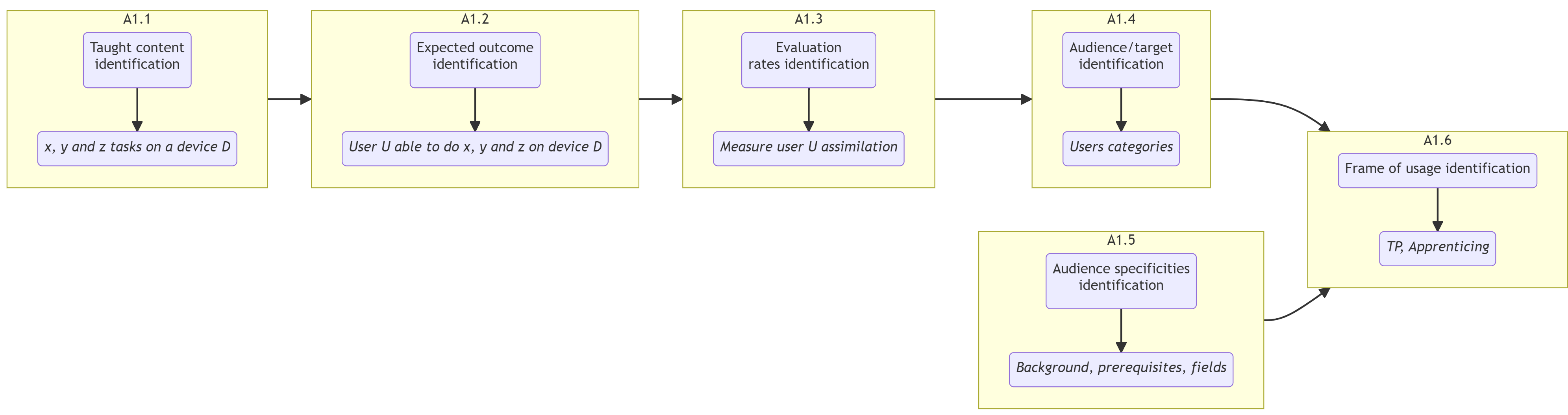 |
Workflow Scope and Audience
- A1.1 - Identify the skills, information and knowledge that need to be taught : x, y and z tasks on a M machine.
- A1.2 - Identify the expected outcomes and results of the training : a user able to do x, y and z tasks.
- A1.3 - Define in which way the success of the training will be evaluated : a rate for the ability of the new user to execute x, y and z without failure
- A1.4 - Express precisely who the training is for: the potential users category, industrial or academic purpose…
- A1.5 - Identify the audience’s existing knowledge and experience : possible related background, prerequisites, fields..
- A1.6 - Determine how the audience will use the training : the frame in which the usage of the training would be required ( TP, apprenticing…)
A2 - Design Learning Content
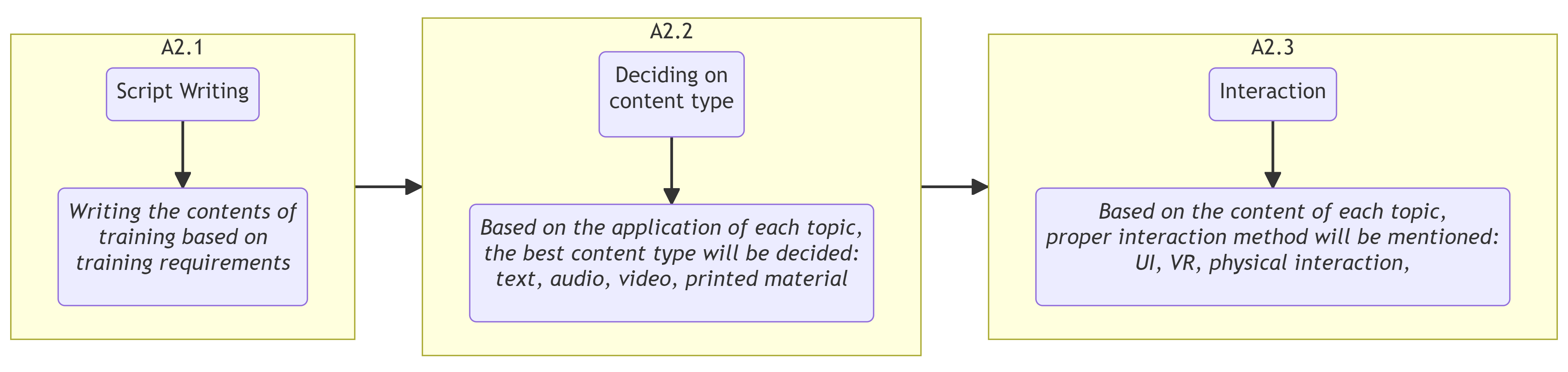 |
Workflow Design Learning Content
- A2.1 - Write a lesson/Course plan that outlines the sequence of learning process : Titled chapters and topicswith descriptions and explanations related to the aim of the training such as guided works, practical works, courses…
- A2.2 - Identify the type of content that will be used : Texts, Audios, images, videos, simulations…
- A2.3 - Determine the interactivity level : clearly express what this learning requires as assimilation, going from the simple theoretical information to the handy/physical manipulation
A3 - Create a Storyboard
 |
Guidelines for Storyboard
|
Workflow Create a Storyboard
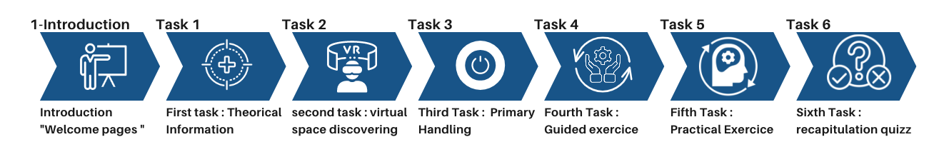
- A3.1 - Design a visual representation of the training process, how you imagine the look of what the user will experience, from the introduction until the end : Start with introductive information followed by tasks to execute and end with an evaluation and a certificate provided.
- A3.2 - Define the interactions taking place within the VR environment: express the gestures, behaviors and all sequenced possibilities happening during the training process.
- A3.4 - Define how the content will be presented : shapes, panels, metaphors used to illustrate and support the content.
A4 - Develop VR Environment
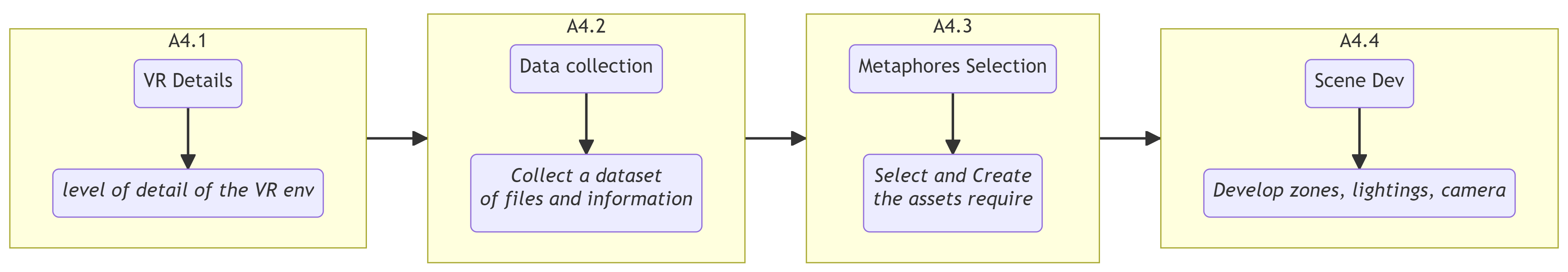 |
Workflow Develop VR Environment
-
A4.1 Determine the level of detail required for the environment according to the main functions :
- Illustrate : how the user will visualize the VR environment.
- Navigate : How the user will circulate and move in the VR environment
- Select : How the user will choose and pick options and functions.
- Manipulate : How the user will interact with objects.
- A4.2 - Collect a dataset of files and information that you will use in your VR environment
- A4.3 - Select and Create the assets required for the environment, this list below gives some suggestions.
- A4.4 - Develop the first scene zones lightings, cameras and textures for the VR environment
A5 - Implement User Interactions
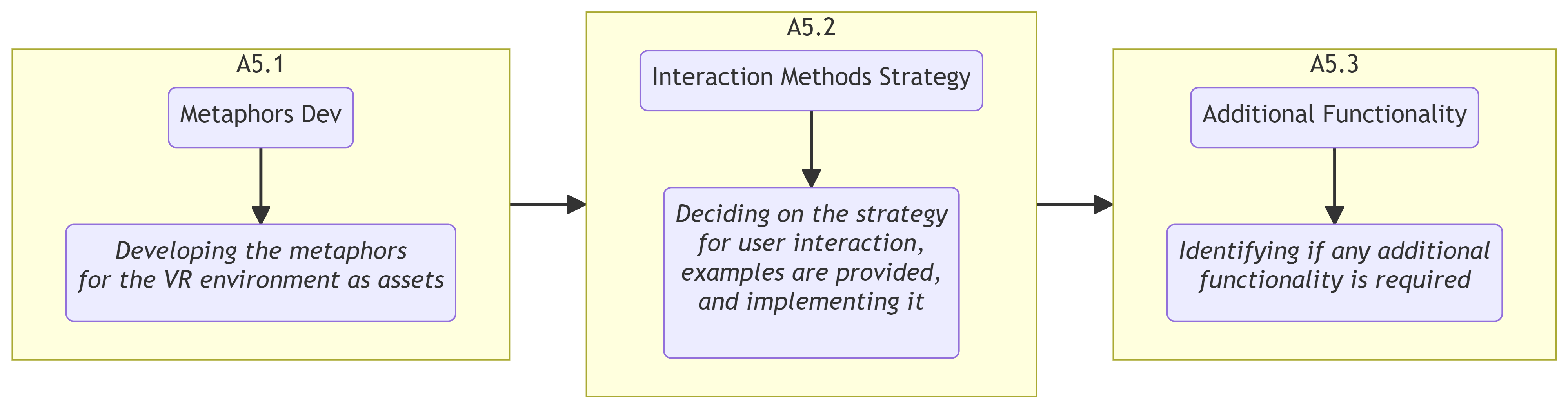 |
Workflow Implement User Interactions
- A5.1 - Develop the metaphors that will be used within the VR environment in the form of Assets.
- A5.2 - Determine how the user will interact with the environment (address a strategy )
- A5.3 - Strategy exemple :
- give clear instructions
- fllow a linear progression of executions (freezing/unfreezing interactions in a sequential way )
- time limits of executions (freezing some interactions after a certain time )
- limited options ( freezing the access of a part of the interactions )
- A5.4 - Identify any additional functionality that is required.
A6 - Test, Launch and Maintain
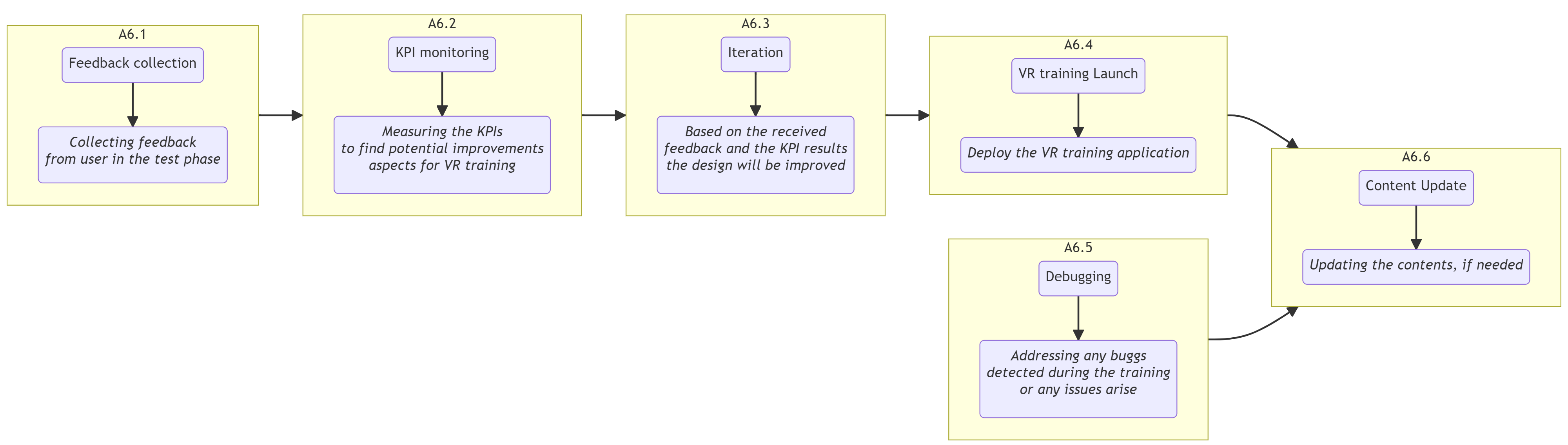 |
Workflow Implement User Interactions
- A6.1 - Collect feedback from users during the testing phase.
- A6.2 - Measurement with KPIS
- A6.3 - Identify areas of improvement for the VR training application.
- A6.4 - Iterate on the design based on feedback received.
- A6.5 - Launch the VR training application.
- A6.6 - Address any bugs or issues that arise.
- A6.7 - Update the content as needed.
Depending on the size and complexity of the requirements for the VR training program as well as the particular needs of the project, different tools may be needed.
Application
A1 - DEFINING THE LEARNING OBJECTIVE AND TARGET AUDIENCE:
The learning objective of this proof of concept is to be an introduction for engineering students of a 5 axis 3D printer and especially the range of movements that can be done by this type of machine.
A2 - DESIGN THE LEARNING CONTENT:
Like the rest of our project the goal is to make this learning and discovery possible and viable through the Unity software and with the use of VR controls.
A3 - CREATE A SCENARIO STORYBOARD:
The storyboard in mind for this use case is quite simple. A student would go into the environment and be able to freely manipulate each axis on the machine within its limitations while having a screen near the machine to provide insight about each part and maybe add some questions to keep a more pedagogic aspect.
A4 - DEVELOP VR ENVIRONMENT:
The first step is then to import the CNC machine into the unity environment, this importation is made in a FBX format. The FBX format can be obtained with the Blender software by converting the cad model in it. Then in the proof of concept scene the first thing to do is to drag and drop the FBX file into the hierarchy area of Unity.
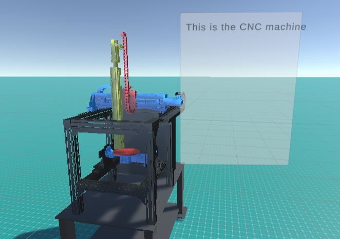
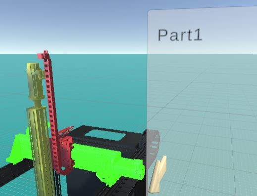
CNC machine scene with colored parts
To keep the parts recognizable between them and be seen correctly through the environment, a material Object from unity has to be created in the adequate folder of your choice in the middle part of the folder explorer (bottom left of the screen). With this material object you can decide which texture and color a object can have and so to directly drag and drop into the part that needs to change color and texture.
The first metaphors to add for a better understanding of the system is to add a highlight system that will show which part is selected in order to manipulate its range of movement.
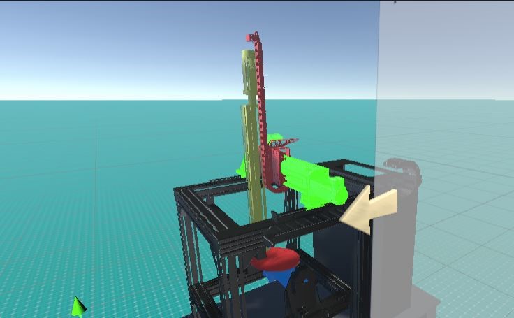
Part highlight and its axis description arrow
The highlighted part is done by dragging and dropping into an array of parts a copy of the part that has been colored with a bright texture. In the screenshot below the number of parts can be changed on the top left to adapt to all types of multipart assemblies.
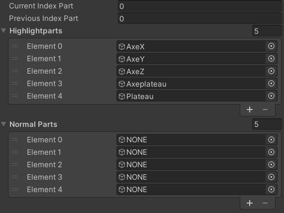
Highlighted part array
Moreover another metaphor to better comprehend in which axis the part highlighted is moving is the use of an arrow that appears during the selection. These arrows are managed by an Object called “managerArrows” that only contains a script that will accordingly activate the arrow that must be placed beforehand by the teacher in the scene manually, the 3d model of the arrow has to be also put in the array made by the script. These arrow models will have to be deactivated in order for the script to work properly. To deactivate any object on unity and just toggle off the box on the top left of the object’s inspector area.
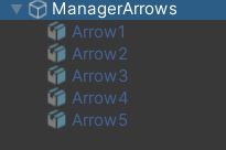
ManagerArrows GameObject (all the arrow object are deactivated)
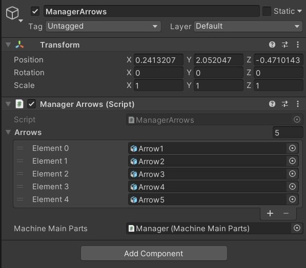
Shown in the inspector (right screen) the array has to be completed with the arrow GameObject
One more pedagogic aspect that we will lean on is the parts description through a basic user interface that will show some text to describe the machine that is presented. As such in this proof of concept the choice has been made to write a script that allows a text entry for each part, in our case there are 5 moving parts so there will be 5 texts that can be shown.
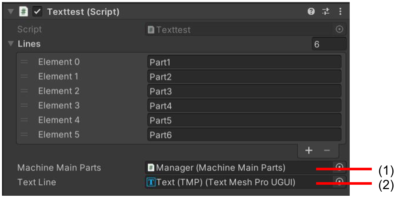
Texttest script for the part description in the UI
In the figure above, in order for the script to work you have to link the manager (1) that we will see just after and the text part of the UI (2) that has to be created and placed by the user in the scene. The UI is a game object that can be created and is linked to a Text entry that can be modified, here the script takes charge of the modification of the text.
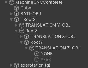
Selected part (element 0) and the corresponding text written on the UI
This topic is more oriented about the overhaul configuration of the system that needs to be studied, as mentioned before the manager will take the main role in that. As such as the highlighting process, another array is available to fill. In this part some data has to be given such as the Gameobject Transform (which is the combination of the 3D model and a set of xyz axis), its movement limit, if it is a rotating part or a translating one and its starting position. In our case each part is linked one to the other as a parent/child hierarchy so the starting position relative to the other piece is (0,0,0). Also the limit is expressed in meters for the translation and in degrees for the rotation.
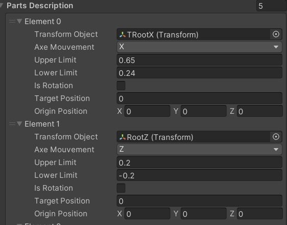
Part description configuration and Machine FBX hierarchy
A5 - IMPLEMENT USER INTERACTIONS:
The most important part, especially for a learning purpose, is to give access for the students to manipulate the machine that they are studying through the VR environment. With the help of the part description script another script has the task to configure the movement of each part by assigning a speed either for rotation and translation to each pieces. as an example the keyboard has been used for this proof of concept due to the availability of functioning VR headset during its development.
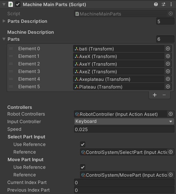
Control setup on the Machine
From the image above , two inputs are configured, that is : SelectPart done with the “up” and “down” arrows and “MovePart” done with the left and right arrows. This reference has to be configured through the script which is the trickiest part of the process. But the packages installed for VR control are also already installed so with external help the part can be adapted for VR controls as seen in the first part of the product.
A6 - TEST, LAUNCH AND MAINTAIN:
The best way to reshape this proof of concept would be to configure the VR movements in the environment and then test the product with teachers and students to refine what can be improved upon, first in the configuration area where someone not versed in the Unity software language could have difficulties and secondly has what feature students liked and didn’t like.
By following the workflow we can then have a good basis on how to make a study of mechanical objects through VR more accessible for teachers and students.
Conclusion
During this project we experienced challenging situations, especially technical issues that we didn’t have any previous experience of facing. Some of these challenges are software version problems of unity, complexity and incompatibility of usage of VR material with some computers, synchronization problems during the push and pull of GitHub, breakdown of the university IT systems at the beginning of the second semester. Another challenge was lack of time and manpower due to absence of one member of the group which led to the alteration of the second objective of the project.
For a better continuance of this project in the future, one suggestion could be to start the Unity or other required software training in the first semester. In this case, students will have more time to tackle technical problems and implement more complex projects in a VR environment.
At the end of this project, the team managed to deliver the requirements specified by the client and this has been done by carrying out continuous meetings with our client and updating the requirements expected by the client.