Realization of a human-machine interface in a collaborative human-robot workplace
1. Objectives
1.1 Main objective of research:
Learn the process of creating a digital twin of a collaborative robot, to achieve its correct implementation in a specific case studied.
1.2 Main objective of application case:
Develop a user-friendly human-machine interface in virtual reality, for training an operator in a workstation shared with a collaborative 7-axis robot.
1.3 Specific objectives:
- Acquire basic notions of virtual reality, its principles, scientific bases, advantages, disadvantages and applications.
- Learn the basic principles to take into account when designing a human-machine interface; according to principles and standards of user-centred design and ergonomics; in order to facilitate the use and learning of this device for users.
- Focus on a specific area of the development process of a project in virtual reality; to be able to apply this knowledge later in the realization of the Avatar collaborative project.
1.4 Objective of the virtual environment:
Serve as an interactive guide or tutorial for the user to learn how to perform an assembly task of a semi-finished product, in a simulation environment before performing the task directly, working with the help of a collaborative robot arm; in his position as an operator on a production or assembly line.
2. Introduction
New and more advanced simulation techniques are now emerging and being refined. Thanks to new technologies it is possible to travel to another world completely different from the real one, the virtual world. This is thanks to virtual reality, which is one of the most powerful technologies for simulating events, tasks and other technologies; and that it is applicable in a large number of fields of knowledge, such as computer science, product design, sales, medicine, tourism, and industry, among many others.
A way to effectively simulate, test and rehearse the activities and operations of an industrial machine without the risks that this entails; it is by creating a digital twin of the machine; however, its creation process is complicated because there must be a communication framework between the real machine and its virtual twin that allows both to behave in the same way; but there is a process known as “Virtual Reality Workflow” that makes this task easier.
All this will be explained in greater depth in this research work, which initially combines documentary research, to apply it later in a specific case of the use of these technologies.
The steps for the creation of a project in virtual reality will be addressed, which entails the creation of the scene, the simulation, allowing interaction, creating the human-machine interface, and the final results adapted to a specific case.
3. Virtual reality
Virtual Reality (VR) describes the set of immersive technologies that seek to position the user within virtual environments simulated by computer. Depending on what the simulations are intended to achieve, the images may or may not be realistic. (Vance & Berg, 2017)
To be carried out, VR makes use of devices called virtual reality glasses or helmets. These make it possible for users to perceive 360° scenes in high definition.
The incorporation of audio and motion sensors allow a unique interaction with the environment, which gives the experience a very useful realistic feature.
Since a user can become the protagonist of a scenario without leaving a controlled environment, the applications in entertainment are only limited by the imagination.
At an industrial level, operators can become familiar with risk environments without exposing themselves, doctors can practice complex procedures, technical equipment can assist remotely, and much more.
Before delving deeper into this technology, it is important not to confuse it with AR (augmented reality).
4. Digital twin
“A digital twin is a virtual representation of an object or system that spans its lifecycle, is updated from real-time data, and uses simulation, machine learning and reasoning to help decision- making.” (Amstrong, 2020)
In plain English, this just means creating a highly complex virtual model that is the exact counterpart (or twin) of a physical thing. The ‘thing’ could be a car, a building, a bridge, or a jet engine. Connected sensors on the physical asset collect data that can be mapped onto the virtual model. Anyone looking at the digital twin can now see crucial information about how the physical thing is doing out there in the real world.
Types of Digital Twin
- Stand-alone digital twins: These are virtual replicas of individual products/equipment. They can help monitor and optimise the performance of individual assets, people, and other physical resources.
- Duplicated digital twins: They help monitor and optimise the use of a combination of related discrete digital twins, e.g., virtual models of multipart systems, such as cars, industrial machines or buildings.
- Enhanced digital twins: These are virtual models of complex and broad entities (e.g., an entire organisation or a city). They are made up of digital twins of their constituent parts. They help monitor and optimise higher-order performance.
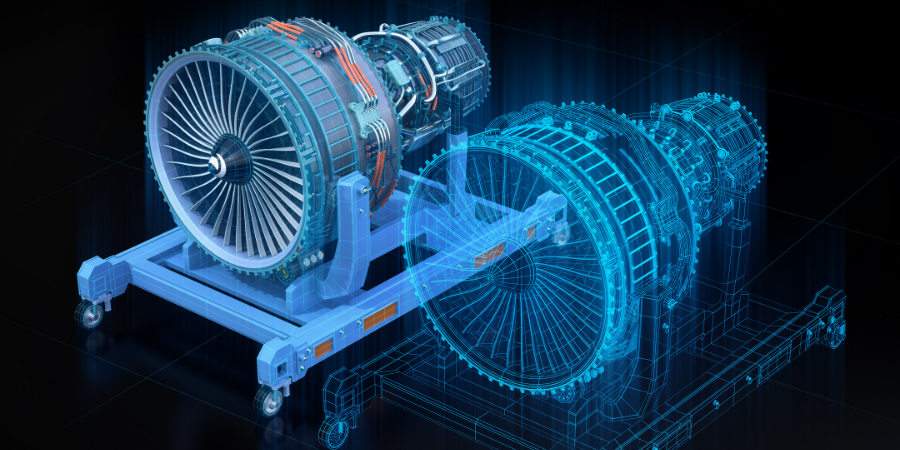
Figure 3. Graphical representation of a digital twin
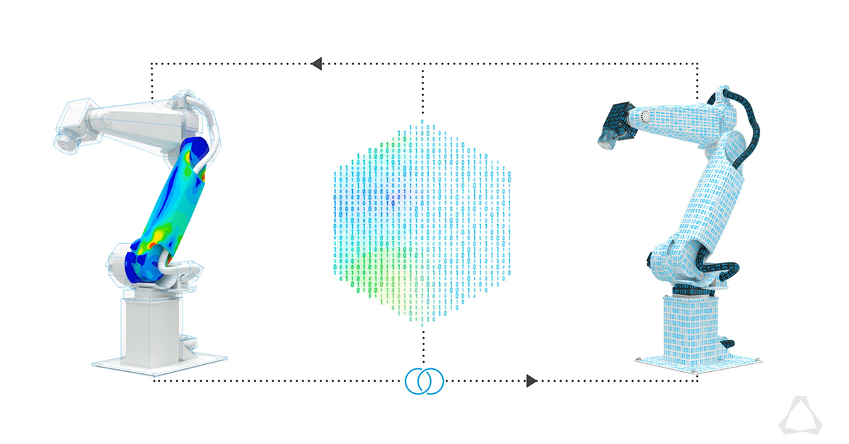
Figure 4. Graphical representation of a structural simulation on a digital twin
4.1 Collaborative robot
A collaborative robot is a robot that works with a human in some way – either as an assistant in a task or process, or as a guide. Unlike autonomous robots, which work largely alone and without supervision, collaborative robots are programmed and designed to respond to human instructions and actions. A collaborative robot is also known as a cobot or co-robot. (Techopedia, 2021)
Although collaborative robots are designed in many different ways, there is a common consensus in the tech industry about what kinds of primary engineering designs and features are used to build them. There is the safety monitored stop, where the robot can temporarily cease operations according to human proximity, and the hand-guiding feature where robots can learn from humans physically guiding infrastructure for a particular process or task. There is also speed and separation monitoring, and power and force limiting, other designs to provide consistent standards for robot performance.
The idea of collaborative robot design builds on the advancement and sophistication of industrial automation – the idea that robots are not just mechanical objects providing repetitive motion, but that they can “learn” and “think” and act along with humans in a true sense. Many of these functionalities are made possible by brand-new technologies and advances in sensor-based learning systems, as well as artificial intelligence that has advanced worlds beyond what it was just a decade ago. Collaborative robots, to many, represent one of the biggest frontiers for the application of cutting-edge technology to enterprise.
4.2 Requirements to create a virtual twin
The first thing to remember when building digital twins is they aren’t just computer models of a physical space. They are directly linked to their associated buildings, transmitting data back and forth in real-time. Digital twin infrastructure can even manage integrated building systems, such as telecommunications networks, content storage platforms, and other enterprise applications. In short, digital twins are extensions of an environment, not static replicas. Designers who keep this guiding principle in mind will forge connections more effectively. (EDS Robotics, 2021)
It’s also helpful to address the size and scope of your digital twin. Will it be the representation of an entire facility or just a few rooms? Smaller spaces will be easier to digitize and refine, while recreating a whole building may require the assistance of specialized partners.
When defining the scope, it can be helpful to create a list of features. It’s important to use the following questions as a starting point:
- What building functions will the digital twin monitor?
- Will the digital twin allow for remote access, or will users need to be on-site?
- Who will operate the digital twin — the general public or employees?
Choosing the AR tools
Once it is known what the digital twin will accomplish, it can be chosen the components that will facilitate it. While doing research, keep the following points into account:
- Information: All digital twins transmit data to and from their physical counterparts. The designer’s task at this point is to choose the most suitable information type. Binary data, such as those powering a lighting system, will be simple and straightforward. Tracking equipment will be far more complex and typically requires specialized hardware.
- Equipment: Digital twins need components that let them achieve their function. This usually includes sensors that can match your intended purpose — for example, location trackers at a hospital are far more useful than seismic monitors from a gas refinery. Designers must also account for physical infrastructure during this stage, such as local cables or a wireless network.
- Enabling technology: Finally, you’ll need software that powers the digital twin. On an architectural scale, solutions that include IoT-based device management and 3D visualizations tend to be the most useful.
Digitally capturing the physical environment
Of course, the most visually impressive part of any digital twin is simulating a physical environment in three dimensions. Whatever is the intent, this requires a digitization process that records the characteristics of a space and generates a 1:1 model. In most cases, someone must move specialized camera equipment from room to room, taking pictures of the area from multiple perspectives. For a large facility, this step can be time-consuming, but every detail you include contributes to a more accurate digital twin.
Once the photography is complete, designers will have a series of images they can assemble into a 3D digital twin building model. At an architectural scale, this is best accomplished with machine learning systems that compile information and automatically note distances between walls, fixtures, and objects. Unfortunately, this is still just a building model — one more step is required before it becomes a full-fledged digital twin.
Bringing functionality to the digital twin
With the completed digital twin architecture on hand, designers must add details and functionality to ensure it operates as intended. These features will vary depending on your intended purpose but might include the following:
- Visual elements: Your initial building model will look much like environments powered by a video game engine — impressive, but still not rendered. Designers may need to include or optimize visual components such as lighting effects or textures. These visuals are particularly important in industries like real estate where end users can tour buildings remotely. (Cropp, 2020)
- Navigation nodes: Indoor navigation is one of the most common uses for digital twins. Designers can use wayfinding and positioning techniques to position end- users within the model or display directional notifications on their smartphone camera.
- Building functionality: Designers can attach interactive nodes to any room or object, granting end-users control of building functions. These might include turning on a light switch, changing the temperature, or activating video conferencing equipment.
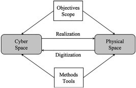
Figure 5. Components of a digital twin creation workflow
Technology worth watching
Digital twins integrate many technologies, such as Artificial Intelligence or Machine Learning. Developments in 3D laser scanning and IoT sensors are building on previous innovations to make a major contribution to the future of digital twins. (Guodong, 2019)
Where there is a visual element, as in the built environment, point cloud processing, scanning technology and LiDAR are central to the creation of the digital twin model framework.
- Internet of Things sensors. Digital twins are made possible mainly due to Internet of Things (IoT) sensors. Integrating IoT capability directly into modules or hardware is set to be a significant market disruptor. This will significantly simplify the setup and deployment of IoT devices and hence the cost to deploy.
- 3D laser scanning software. One of the unsung heroes of digital twin technology is reality capture. Vector-based, multi-stage point cloud processing (or stitching) is providing the visual data for digital twins. You can learn more in our guide to point cloud processing.
- AI and Machine Learning. Given the vast amount of data produced, artificial intelligence and machine learning are the only way to analyze the model of operations represented by the digital twin. For digital twins to deliver on their promise, they must be able to run analytics in real-time or faster, provide a high degree of prediction accuracy, and integrate data from a collection of disparate and often incompatible sources.
- 5G Connectivity. Underpinning every digital twin use case is connectivity. 5G is becoming a key component. 5G promises a range of capabilities that will transform digital twin capabilities: low latency, high bandwidth, high capacity, strong reliability, advanced mobility and longer battery life. For example, a 4G network can support up to 5500 to 6000 IoT devices on a single cell. With a 5G network, up to one million devices can be handled.
- Cloud Computing. Cloud technology provides the means to process and run digital twins. Microsoft already provides a growing range of Azure Digital Twin products to help with this objective. In contrast, Amazon Web Services (AWS) is offering a “Device Shadow” service as part of their AWS IoT line-up. Many more will follow.
Here are a few other recommendations to follow:
- Set aside a budget for testing digital twins and other related technologies
- Experiment in areas that have already been successful elsewhere
- Research technologies needed for digital twins
- Reach out to experts to explore digital twin technology
5. Proposed project
5.1 Project subject
My project consists of the development of a user interface for training in a shared workstation between the operator and the collaborative robot using virtual reality. Using a virtual environment where the user will complete at task of assembling a product; for which two pieces must be joined together. The workstation consists of a central rectangular work table, in front of it the robot is placed. At each end of the table there are two conveyor belts; one takes the products in process to the table, and then the other one takes the finished products.
In better illustrate the task that should be fulfilled by the cobot and the operator, you can find an analytical curse diagram chart, it is a chart adapted from a bimanual diagram from the OIT texts about work organization:
Operator and collaborative robot analytical tasks chart:
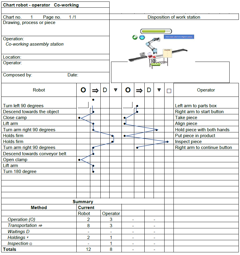
Figure 6. Operator and collaborative robot analytical tasks chart, from the OIT bimanual chart
After understanding the task, you will find a sketch of the system from the operator view here under, you may notice the cobot in the centre of the workstation, behind the worktable, at each side of the robot one conveyor line, one brings the products to the workstation, and the other takes the final products away.
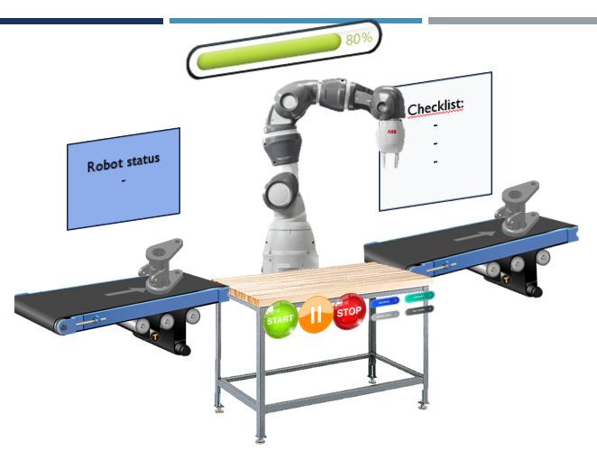
Figure 7. Schematic proposition of the workstation design
In order to accomplish with the task, a process has been followed, that is the virtual reality workflow process; that allows to create a digital twin by following those steps. The process that has been followed is detailed in the next parts of the research paper, from Scene creation, to
5.2 Step One: Scene creation
The scene creation consists in creating the environment that will be used for the virtual reality simulation experience, it consists in create the virtual world in general, so that the user can feel that he/she ais completely immersed in. (Terkaj, y otros, 2022)
For the scene creation making, I used two different ways to create the environment, which would look like an industrial facility; first for the general environment, to create the facility big features; I created a plan which would be the floor of the plant, and I changed the texture of the floor; then I used some basic 3D shapes like cubes, that I then enlarge to create the four walls of the facility; then I imported some big furniture from the Unity community free to use CAD designs; from Bos shelves, to a carriage, to a forklift; and a two level structure with stairs.
Then for the more specific part if the scene creation; I designed some pieces of furniture that would be used in the workplace, for example two conveyor belts, one worktable, and the base in which the cobot would be mounted, these pieces of furniture were designed using the software Fusion 360 from Autodesk. You might see the scene creation pictures here:
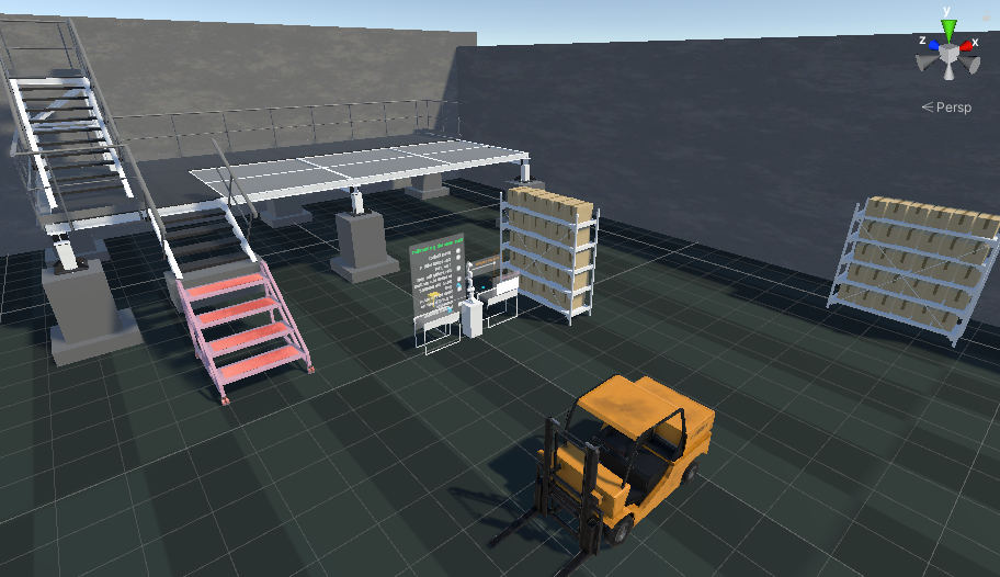
Figure 8. Industrial Facility Scene
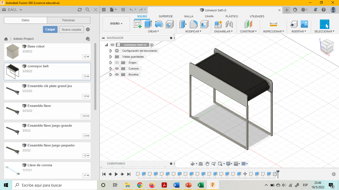
Figure 9. Conveyor belt designed in Fusion 360
5.3 Step two: Simulation
After creating the scene in which the users will be immersed, it is important to add some characteristics or features that would represent solid objects, for example, till this moment the worktable is only visible, but nothing can be placed over it, nor it can be interacted with, In order to add some realism to the environment, all the furniture must be configured to be solid; so this objective, some box-colliders were added and adjusted to the size of each furniture piece, that is really important for the workstation interaction. (Terkaj, y otros, 2022)
In addition, the pieces that would represent the product and piece to be assembled were added, and box colliders were added to them too; as well as kinematics laws so they physically behave as the would in reality, also it was added the features “grab interactable” so they could be grabbed by the user.
On the other hand, the collaborative robot Franka Emilia structure, model, and scripts behaviour were imported, as well as its trajectory previously defined taking into account the different workstation measures. The robot was configured to first of all, grab the piece from the feeding conveyor belt, then turn 90 degrees and put the piece in the worktable, so the operator can assembly it with another piece; and finally, the robot picks again the finished product from the operator worktable, and turns another 90 degrees, so it positions himself in over the carry away conveyor belt; and finally, it deposits the finished assembled piece in the conveyor belt. It is used the software Json, and a script which registrates the position and rotation of each robot joint at each moment. Operations performed by robot:
- Pre-grasp, grasp, pick up, pre place, place, place up, pick place done.
You may see below, the representation of the robot, and a similar scheme of the joints of a cobot.
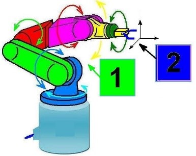
Figure 10. Graphic representation of a cobot joints rotation
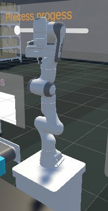
Figure 11. Franka Emilia Robot model imported
5.4 Step three: Interaction
In order to be able to interact with the environment, it is necessary to configurate a self- representation on the virtual world; that is concretised by adding an “X-rig” object in the project structure; it contains the representation of the user, by using a camera, that represents the virtual reality glasses, and help track the movements of the user at each moment; and the representation of each hand, by the use of two hand controllers. (Terkaj, y otros, 2022)
The right hand was configurated so that it can grab distant objects by using a ray cast beam; and get them near or away. The other hand controller allows to grab objects directly only, and to be able to use teleport to displace.
To allow movement of the user, two ways were included, first it is allowed to move by walking normally, and also by teleporting to another place in the environment; to achieve this last option, the installation of a teleport area plane was needed, that covered the entire facility plane area. Then the installation of one teleport anchor were made, so that the user can teleport easily in front of the workstation, and being correctly standing in their workplace.
Also, as it was mentioned before, some pieces were configurated to allow the user to grab them. A representation in pictures of the interaction process and the interactable objects is showed below:
18
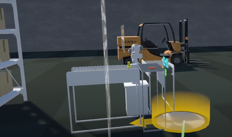
Figure 12. Teleport area option
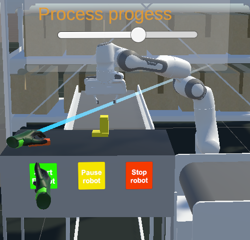
Figure 13. Hand grabbing a product
5.5 Step four: UI creation
To be able to accomplish its objectives of serve as a tutorial to train new operators in the production line; some kind of direct control from the user over the robot and the process is required; as well as the literal description of the tasks that must be performed to the operator.
To better understand this principle and the creation of a human-machine interface, it is first necessary to understand the context a bit, by reviewing some basic definition and HMI principles in the following part.
5.6 Human-Machine Interaction
I focused to study the human-machine interaction, discipline that studies how users interact with computer technology.
It studies the exchange of information between people and computers. Its goal is to make this exchange more efficient: it minimizes errors, increases satisfaction, decreases frustration and, ultimately, makes tasks involving people and computers more productive.
It studies the design, evaluation and implementation of interactive computing systems for human use, and with the study of the most important phenomena with which it is related.
There is still no concrete definition for the set of concepts that make up the area of human- machine interaction. In general terms, we could say that it is the discipline that studies the exchange of information between people and computers. This is responsible for the design, evaluation and implementation of interactive technological devices, studying the greatest number of cases that may affect them. The goal is to make the exchange more efficient: minimize errors, increase satisfaction, decrease frustration and, ultimately, make the tasks that surround people and computers more productive. (Deckonick, 2021)
5.7 Principles of human-machine interface design
- What are the principles of a good human-machine interface?
- Using Fundamental psychology for interaction design: People hold information in two different streams in their heads: The Visuo-spatial scratchpad holds shapes and images while the phonological loop holds words and sounds. Example using icons alongside labels: Icons provide a shortcut once meaning has been reasoned. Frees up the user to concentrate on other new information. (Bath Institute of Medical Engineering, 2016)
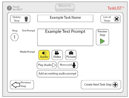
Figure 14. Menu interface with written and graphical buttons
- Using Fundamental psychology for interaction design: Paradoxes in Designing for the Human Mind: Depth vs. Breadth The finite nature of the mind’s attention requires that there are as few elements on the page as possible, but spatial awareness requires that there are as few pages as possible. (Bath Institute of Medical Engineering, 2016)
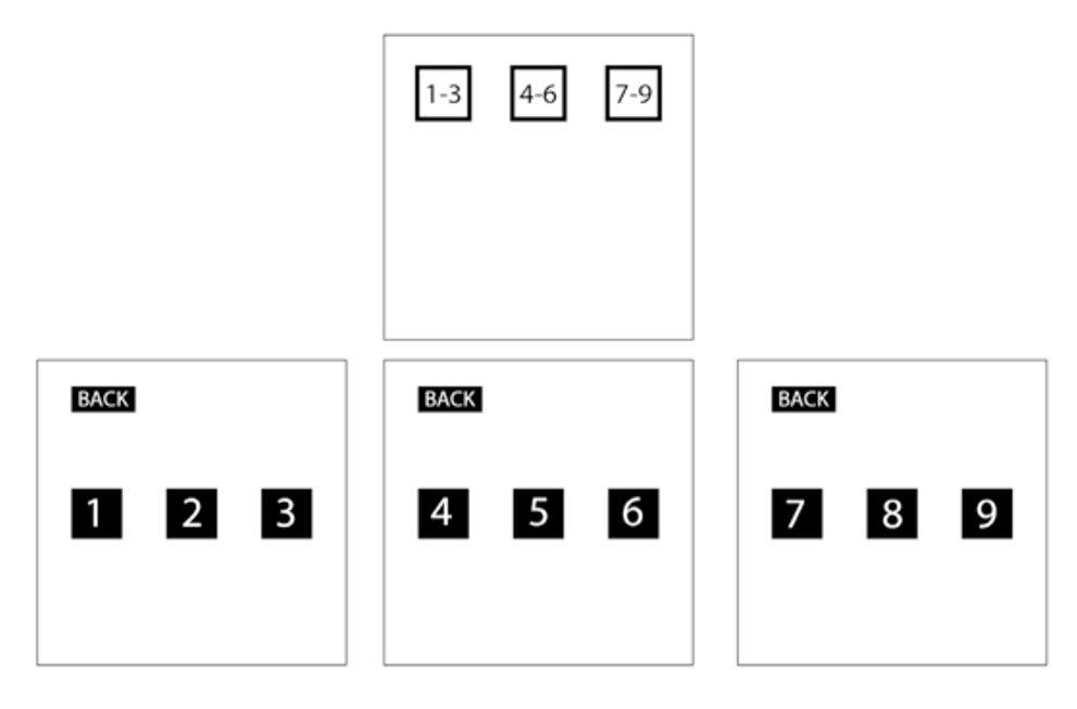
A Deep interface (on 4 separate screens)
- Typical interaction design solution for the Depth vs. Breadth Paradox: A tab system shows users:
- current and most important information
- all the options are still available
- map or structure of the interface (permanent buttons)
- Using the fundamental model of learning for interaction design: Examples where this theory is used in interaction design
- interface designs emphasize learning by doing
- sometimes even using ‘overlearning’ (reinforcing earlier procedures by using them during future exercises)
- Using the fundamental psychology of learning for interaction design: For example, Spaced Retrieval technique for embedding learning in the long-term memory
- Proposed intervals in a spaced retrieval scheme (revision of the tasks learnt)
- Ever-increasing periods of time between each revision
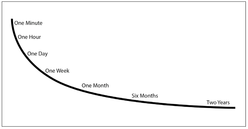
Figure 16. Proposed learning times according to Spaced retrieval technique
- Using the fundamental psychology of learning for interaction design:
- For example, scaffolding technique: used in education to gradually build up a learner’s confidence in a new skill. For the Task Sequencer product: three different lessons. (Bath Institute of Medical Engineering, 2016)
- step-by-step introduction of how to create a task with the user only able to move from one page to the next.
- guides the user step-by-step through the process but tells the user what to write in each field.
- step-by-step through the creation of the first task and allows them to input their own information into the fields.
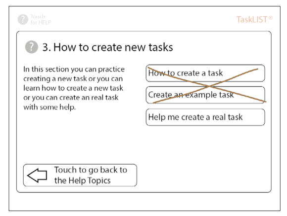
Figure 17. Proposed task training according to the scaffolding technique
- Jacob Nielson’s 10 heuristics:
- Visibility of system status: The system should always keep users informed about what is going on, through appropriate feedback within reasonable time.
- Match between system and the real world: The system should speak the users’ language, with words, phrases and concepts familiar to the user, rather than system-oriented terms. Follow real-world conventions, making information appear in a natural and logical order. (Deckonick, 2021)
- User control and freedom: Users often choose system functions by mistake and will need a clearly marked ‘eemergency exit’ to leave the unwanted state without having to go through an extended dialogue. Support undo and redo.
- Consistency and standards: Users should not have to wonder whether different words, situations, or actions mean the same thing. Follow platform conventions.
- Error prevention: Even better than good error messages is a careful design, which prevents a problem from occurring in the first place. Either eliminate error-prone conditions or check for them and present users with a confirmation option before they commit to the action.
- Recognition rather than recall: Minimize the user’s memory load by making objects, actions, and options visible. The user should not have to remember information from one part of the dialogue to another. Instructions for use of the system should be visible or easily retrievable whenever appropriate.
- Flexibility and efficiency of use: Accelerators - unseen by the novice user - may often speed up the interaction for the expert user such that the system can cater to both inexperienced and experienced users. Allow users to tailor frequent actions.
- Aesthetic and minimalist design: Dialogue should not contain information, which is irrelevant or rarely needed. Every extra unit of information in a dialogue competes with the relevant units of information and diminishes their relative visibility.
- Help users recognize, diagnose, and recover from errors: Error messages should be expressed in plain language (no codes), precisely indicate the problem, and constructively suggest a solution.
- Help and documentation: Even though it is better if the system can be used without documentation, it may be necessary to provide help and documentation. Any such information should be easy-to-use.
5.8 Project interface proposition
The task specifically goes as follows:
First the operator presses the start button to order an in-process product; after this the robot picks up an in-process product from the in-feed conveyor belt; it turns a half turn and holds the product in front of the operator; the operator picks up a part from a compartment in his/her table, and then he/she places another missing part on it; the operator inspects, and then presses continue; thus, the robot turns a half turn and deposits the finished product on the receiving conveyor belt. Finally, the robot turns 180 degrees on the vertical axis and is ready to start the process again.
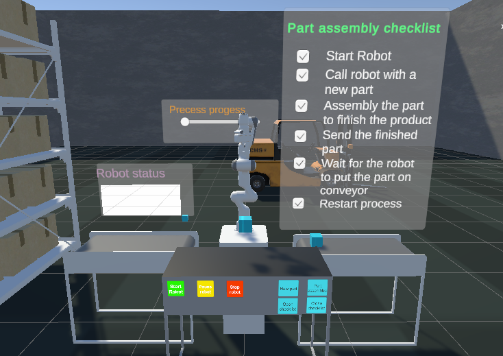
The proposed interface consists of a series of panels and controls, which will tell the operator what to do.
First there will be a panel that will show a checklist of the steps to be completed, which will be ticked off as the learner progresses through the tasks.
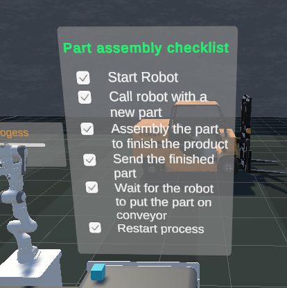
Figure 18. Task’s activities checklist
Second, there will be start, pause, continue, restart and back buttons to give the operator a sense of control according to the basic principles of how to create a human-machine interface. These buttons will have two ways of being displayed; the first with symbols and text; and the second, symbols only; when the operator gains training and knowledge in the process. In addition, according to another principle or rule of interface elements, a robot status panel will be created to display the robot status textually to ensure that the operator is aware of the status at all times. In addition, a progress bar will be included, so the operator will know how much progress has been made and how many tasks are still to be completed.
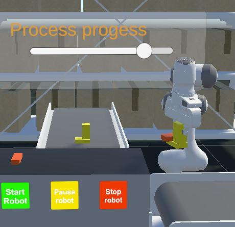
Figure 19. Scrollbar showing task completion
The third way of facilitating human-machine interaction will consist of creating visual signals, such as spaces or objects that glow; where the operator must pick up, place the pieces; and also, the product will change colour if the manufacturing processes have been carried out correctly; and there will also be sound signals at the same time, thus assuring the worker that the process has been carried out in the right way.
You can see the final design of the Human-Machine interface design below:
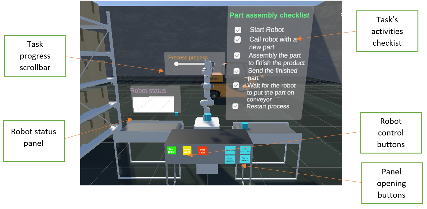
Figure 20. Workstation training final interface design
5.9 Project final results
When trying to obtain a good result, the most difficult part was to achieve the robot to correctly grab the piece, and to follow the already configured trajectory; it was specifically difficult because the size of the conveyor belts and the worktable did not fit those from the robot trajectory; so, in the lasts moments, the size of the different furniture had to be modified, so the tasks were performed correctly.
The results were successful in general, and the main objectives of the project were fulfilled; it was easy to understand the task, and follow the indications of the checklist; also, the interaction with the robot were good, the robot understood the different commands of the user and performed the task.
The final results allow a user to be able to immerse himself in an industrial plant, to know a little about what a job is like in an industrial line of work, in collaboration with a collaborative robot to be able to assemble a part on a product in process. The designed tutorial allows to know the interface of the workstation, to use the robot correctly and at the same time to learn step by step to carry out the assembly task.
Among the possibilities for improvement, the main thing would be to be able to continue research to be able to implement fluid communication between the physical robot software and its digital twin in simulation software; and thus, be able to have real-time information from both sides and implement the same actions on the other side. It would also be convenient to be able to carry out more robot movement trajectories, or even greater autonomy so that it can search for the position of the piece to be picked up; this would complete the project in its integration phase.
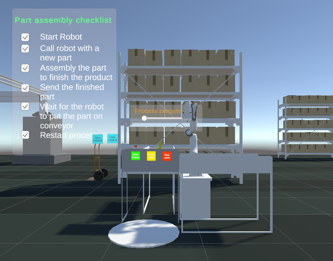
Figure 21. Final workstation design and disposition of Human Machine Interface
6. Conclusion
Virtual reality is one of the most advanced simulation technologies today; since it has an application in many domains of knowledge, and facilitates learning, research and economic activities. It has many advantages, since it helps to identify design problems before the manufacture of an object, which helps save costs; or it helps to carry out risk-free simulations associated with a real test. The use of virtual reality technology requires the care of several technical aspects, from the advanced hardware used, the need for position and pressure sensors, among others; and specialized software. Likewise, a good virtual staging must follow a process that facilitates its creation; where the steps of creating a virtual scene, virtual simulation, enabling interaction with objects, the integration of a correct human-machine interface, and the integration of all the components to create an animated virtual scene are included.
In the present work, the use of this procedure for the application to a specific case was exposed: the training of a collaborative assembly task between a human and a collaborative robot. The results were satisfactory in relation to the time available, creating a user interface for an assembly work tutorial in a collaborative workstation between a human and a robot; which shows that this process is very useful to obtain satisfactory results in a limited time, and allows to serve as a guide for the elaboration of this type of projects.
7. Bibliography
- Amstrong, M. (2020). What is Digital Twin? San Francisco: IBM.
- Bath Institute of Medical Engineering. (2016). Interaction Design. Bath: Bath Institute of Medical Engineering.
- Craftsman (Shanghai) Intelligent Technology Development Co., Ltd. (12 de October de 2019).
- Craftman: Four Key Elements of Virtual Reality. Obtenido de Craftman: Four Key Elements of Virtual Reality: https://www.weldingsimulators.com/info/four-key-elements-of-virtual- reality-41965032.html
- Cropp, C. (2020). How to make a digital twin: the options, types and outputs. London: Vercator. Deckonick, E. (2021). Interaction Design. Bath: University of Bath.
- EDS Robotics. (04 de August de 2021). EDS Robotics : Realidad Virtual, ¿qué es y qué aplicaciones
- Euroinnova. (25 de May de 2018). Euroinnova: International Online Education. Obtenido de
- Euroinnova: International Online Education: https://www.euroinnova.edu.es/blog-que-es-la-realidad-virtual#iquestqueacute-es-la-realidad-virtual
- Guodong, S. (2019). Framework for a digital twin in manufacturing: Scope and requirements.
- Gaithersburg: National Institute of Standards and Technology.
- Ma, D., Gausermeier, J., Fan, X., & Grafe, M. (2011). Virtual Reality & Augmented Reality in
- Industry. Shanghai: Shanghai Jiao Tong University Press.
- Techopedia. (18 de August de 2021). Collaborative Robot (Cobot). Obtenido de Techopedia: https://www.techopedia.com/definition/14298/collaborative-robot-cobot
- Terkaj, W., Greci, L., Mondellini, M., Sacco, M., Urgo, M., Colombo, G., . . . Martin, S. (2022).
- Advanced Virtual and Augmented Reality Toolkit for Learning. Grenoble, Milano, Belgrade.
- Tom Dieck, C., & Jung, T. (2019). Augmented reality and virtual reality. Cham: Springer Nature Switzerland.
- Vance, J., & Berg, L. (2017). Industry use of virtual reality in product design and manufacturing.