A1.1 - Parts Modeling
Starting from existing references (i.e., technical datasheet) it is possible to reproduce 3D assets representing industrial equipment and products in a traditional CAD environment. This route is recommended in those cases when ready-made 3D models cannot be found in the OEMs resources or through online libraries (i.e., GrabCAD). Another potential issue can be related to restrictions in terms of rights of use and privacy policies, since manufacturers that make their 3D models available for download may not allow to publish any result even for non commercial use.
Herein, the example of a vibrating bowl is available both as a .STEP file originally exported from a traditional CAD envirnoment (e.g., Solidworks) and as a .glTF. It is presented as one multibody part (beside the bowl itself, it includes the feets, plus a lateral funnel for parts feeding, etc.). Moreover, it is recommended to prioritize the remodeling of visible components only, skipping the hidden ones (e.g, the vibrating motors) that would not be visible anyway once imported in the VR scene, as well as the tiny ones (bolts, nuts, etc.).
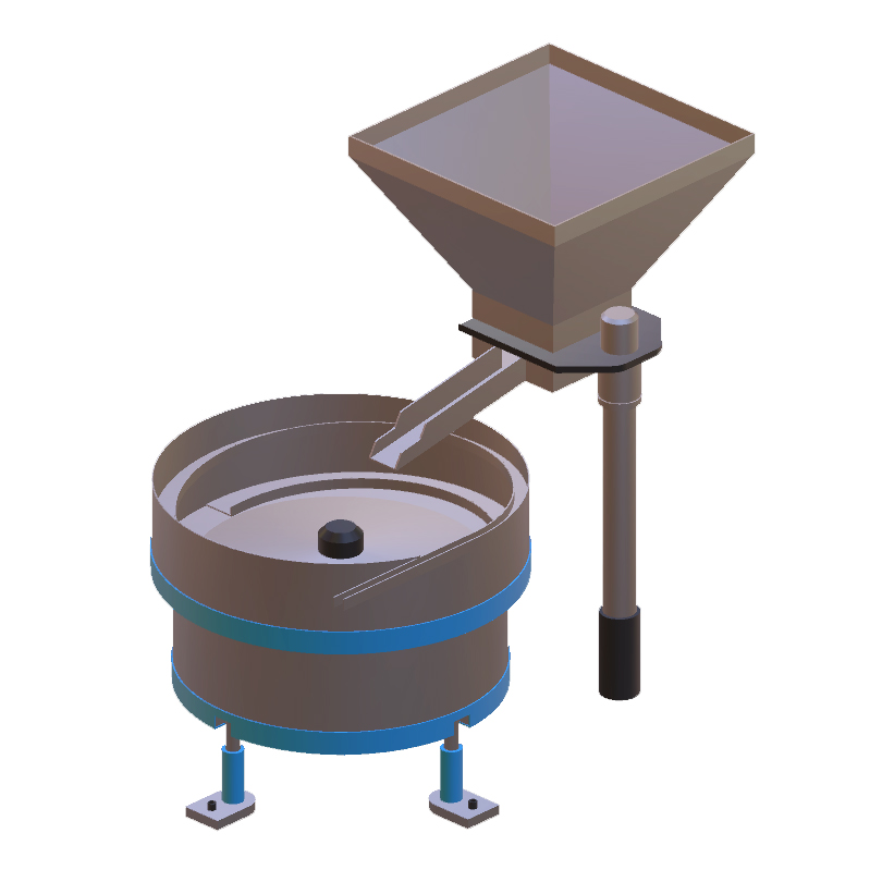
Vibrating bowl model with basic materials
Another aspect to take into account is the consistent definition of reference points (i.e., the origin) for each elementary part: specifically, when considering the bounding box of parts, a univocal position for its origin should be considered. For the case of the vibrating bowl, the center of the bottom face of its bounding box was chosen, as shown in the image below. The same logic must be applied to all elementary parts that will make up more complex assemblies that will populate the VR scene. Notice that this operation can be carried out either in the context of this A1 activity from the CAD sofware by displacing bodies relative to the origin (e.g., Move/Copy Bodies feature in Solidworks) as well as in a the A4 step when dealing with the exported asset in .glTF format inside a mesh editing tool like Blender. An automatic bounding box generator for Blender to be installed from the Edit/Preferences/Add-ons section is provided below as a Phyton code.
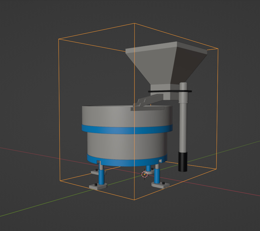
Vibrating bowl with origin at the center of the bottom face of its bounding box
Input
Existing system references (e.g. technical datasheets., drawings, operating manuals, etc), internal 3D models or existing 3D models from Original Equipment Manufacturer OEM resources or online libraries (if available and permissible to use).
Output
File formats like .STEP (for CAD environment) and .glTF (for mesh editing tools)
Control
Assembly of the sub-parts within the main part, support of the 3D file exported with the VR rendering engine.
Resources
- Technical information
- CAD Softwares
- Modeling Softwares