Digital Human Modeling
Research on digital human models first began in the 1980s for the purpose of creating a body template for design drafting. With the development of computer-aided design software, human templates were transformed digitally. The digital human body template usually has the following characteristics:
- has different dimensions and can be used to represent different human races
- can be used to simulate the movement of the human body
- can be used for quantitative evaluation of human-machine interaction.
(Mochimaru, 2017) There are a number of commercial software packages available to support the creation of digital human models, such as Jack and Ramsis, which are often used by companies experts or researchers who are familiar with ergonomics. To use these softwares, usually, the first step is identifying the target user (persona in the human-centered design process), then determining the anthropometric data of the human model based on the target population. After the human model is complete, body movements of the model are then created in a virtual environment, either by inverse kinematics of each body segment or by using a motion capture system. The whole movements represented by the virtual human can then be analyzed in detail by the software, e.g., Reachable areas, viewable areas, joint angles, time spent on the whole movement, etc. However, these softwares can only keep the analysis at a body surface level. Luckily, the new generation of digital body software like Anybody, Santos, can already support the in-depth analysis of the musculoskeletal system, introducing a biomechanical basis for the usability assessment.
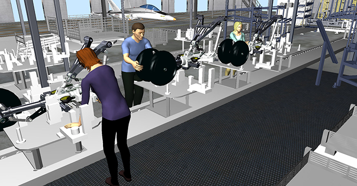
Figure 1. Jack Screenshot Credit Link
Many multinational companies have a wide distribution of users around the world, and they will optimize their products locally for specific markets. In a usual product development process, before product release, ergonomic testing always a good option to help product designers assess the experience of the new product. However, to conduct ergonomic testing, it is necessary to find specific target users which need to cover the percentile of anthropometric data. This is not easy for most companies to achieve. Although software such as Jack is available to assist with analysis, but such software is often not intuitive enough to obtain a subjective experience from a first-person perspective.
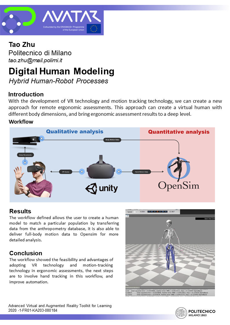
With the development of VR technology and the digital human technology, we can solve the above problem very well. VR technology can give the test user an immersive experience. Digital human technology can generate mannequins of different sizes and populations, so one user can experience the perspective of different populations. In addition, we can capture the human movements with a motion capture system and hand over the data to the biomechanical analysis software like Opensim for analysis. Predictably, this workflow solves the pain point of screening test users and brings quantifiable data to support ergonomic testing.
Poster
Workflow development
| CONTROL: Quality and detail of the generated 3D human body surface model, accuracy of anthropometric data used for modeling, motion tracking quality and accuracy | ||
| INPUT: Chosen engine and modeling software, user data for modeling | 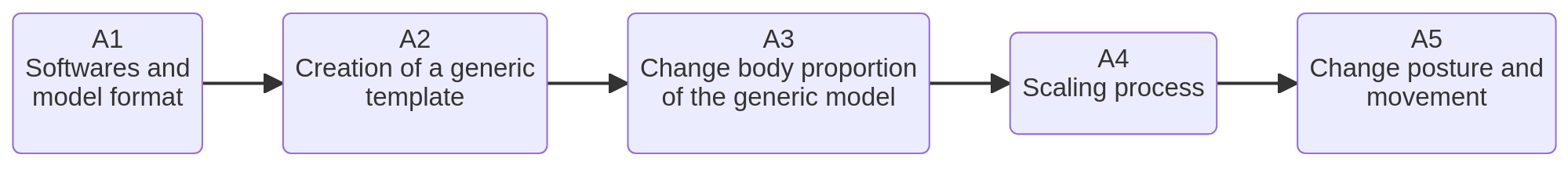 | OUTPUT: 3D model with motion tracking |
| RESOURCE: Anthropometric toolkit, 3D modeling software |
Workflow Building-Blocks
Human body surface model
This section focuses on the creation of human surface models and how to create generic mannequins that can be scaled to meet usability testing or ergonomic assessments.
| Acitivities | Overview |
|---|---|
| A1 Softwares and model format | • Description: In general, all the modeling software can be used to create the human body surface, but these softwares supports different formats export. Therefore, in order to choose the right modeling software, the first thing is to consider the compatibility of the development engine which is going to be used. Typically, most development engines (Unity, UnReal, Babylon.js, Three.js) support mesh models. What exactly is a mesh model? Mesh models use vertices, edges, and faces to form polygons such as triangles and quadrilaterals to represent complex 3D shapes. Unlike solid models, mesh models have no mass information. The popular modeling software that can be used for creating 3D human models are Blender, Makehuman, Maya, 3Ds Max, Mudbox, ZBrush. Modeling software commonly used in the industry world can also be used to create simple human surface models, such as SOLIDWORKS, CREO, CATIA, NX, Parasolid. But since most of the software on the upper list is commercial software, the accessibility of them is not easy, therefore going with an open-source solution might save many resources. Blender is a powerful open-source modeling tool that covers all modeling processes, modeling, rigging, animation, simulation, rendering, compositing, even for complex tasks like motion tracking, video editing, and 2D animation it also helps. • Input: Chosen engine (Unity, UnReal, Babylon.js, Three.js, etc.), modeling software to be used (Blender, 3Ds Max, Solidworks, etc.) • Output: A 3D human body surface model in a format that is compatible with the chosen development engine • Control: Quality and detail of the generated 3D human body surface model • Resource: Modeling software (Blender, Makehuman, Maya, 3Ds Max, Mudbox, ZBrush, SOLIDWORKS, CREO, CATIA, NX, Parasolid, etc.) and development engine (Unity, UnReal, Babylon.js, Three.js) |
| A2 Creation of a generic (template) body surface model | • Description: Before creating a generic human body template, it is necessary to summarize the requirements for making a human body surface, and in interviews with many designers, a lot of useful feedback was gathered. 1. The human body template should be easily scalable so that, so that it can be scaled once the designers have obtained the anthropometric data of the target user. 2. Clear body joints to allow designers to place skeletal joints 3. follow a common human hierarchy to ensure the readability of the model. It is useful to make a preliminary search, also to prevent rebuilding the wheel. 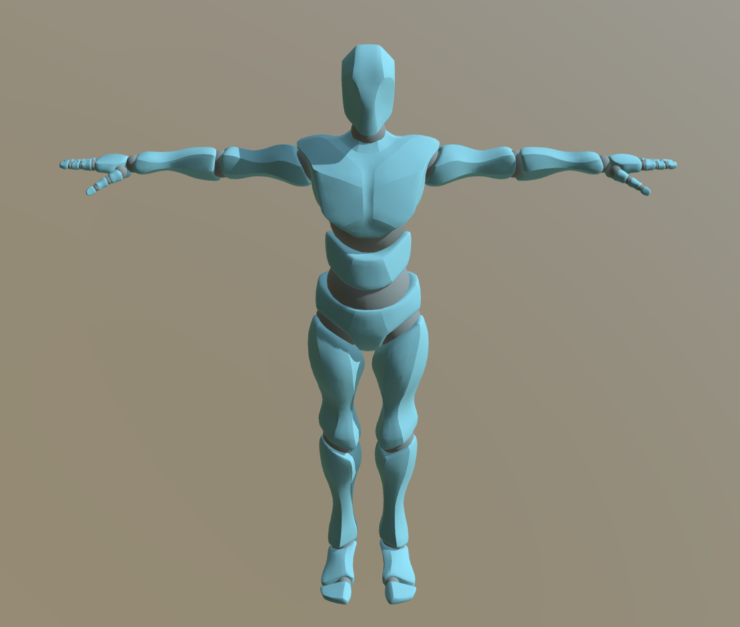 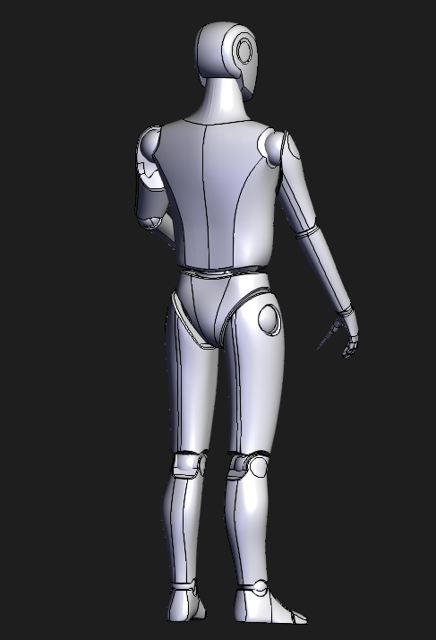 The final model created is shown below and as can be seen, the template model follows a clean design language and divides the model’s layers according to a common human hierarchical structure. This hierarchical method divides the human body into 11 regions, (Przednowek, 2014), as shown in the diagram. 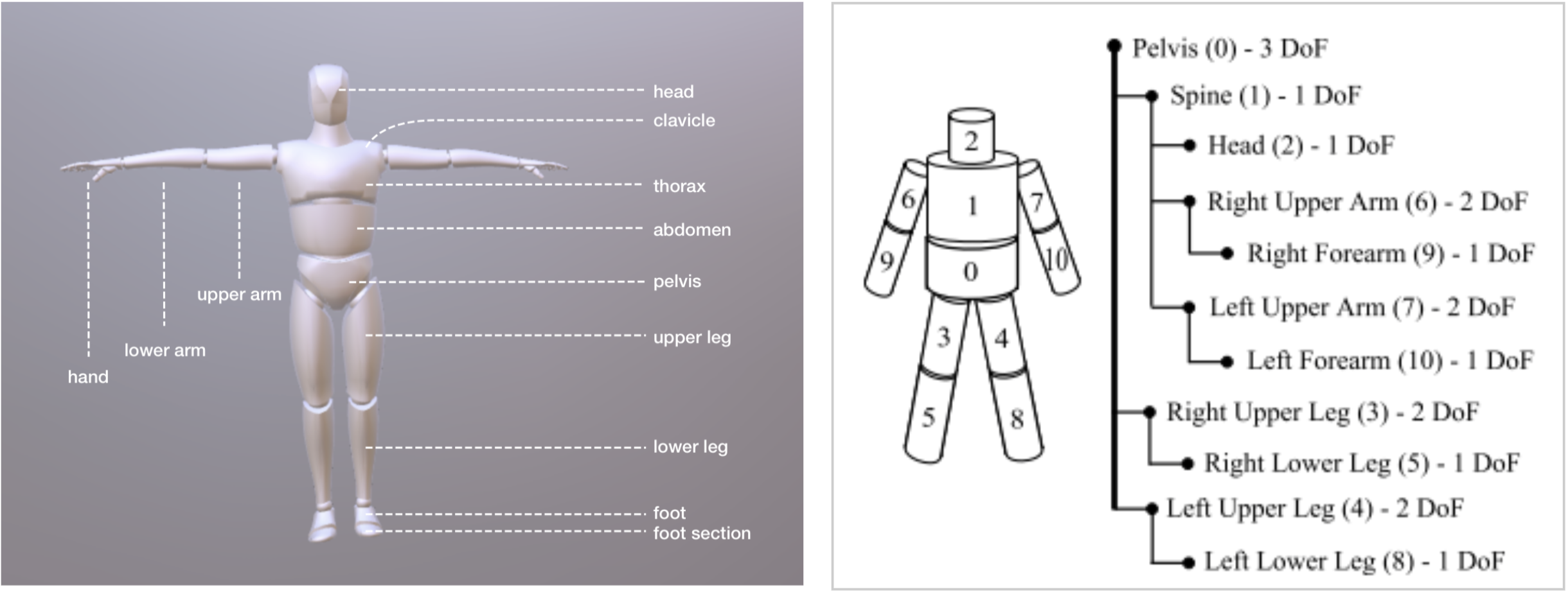 • Input: Requirements for creating a human body surface, anthropometric data of the target user for scaling purposes • Output: A scalable generic human body template with clearly defined body joints • Control: Quality and readability of the final model • Resource: 3D modeling software |
| A3 Change body proportion of the generic model | • Description: In order to be able to test ergonomic factors in a virtual scene using a generic template model, it is required to scale the body parts of the mannequin. The scaling process requires anthropometric data input. For this purpose, a data provided by TU Delft is used: Dined is an online anthropometric toolkit that supports anthropometric data from Dutch, Italian, American, etc.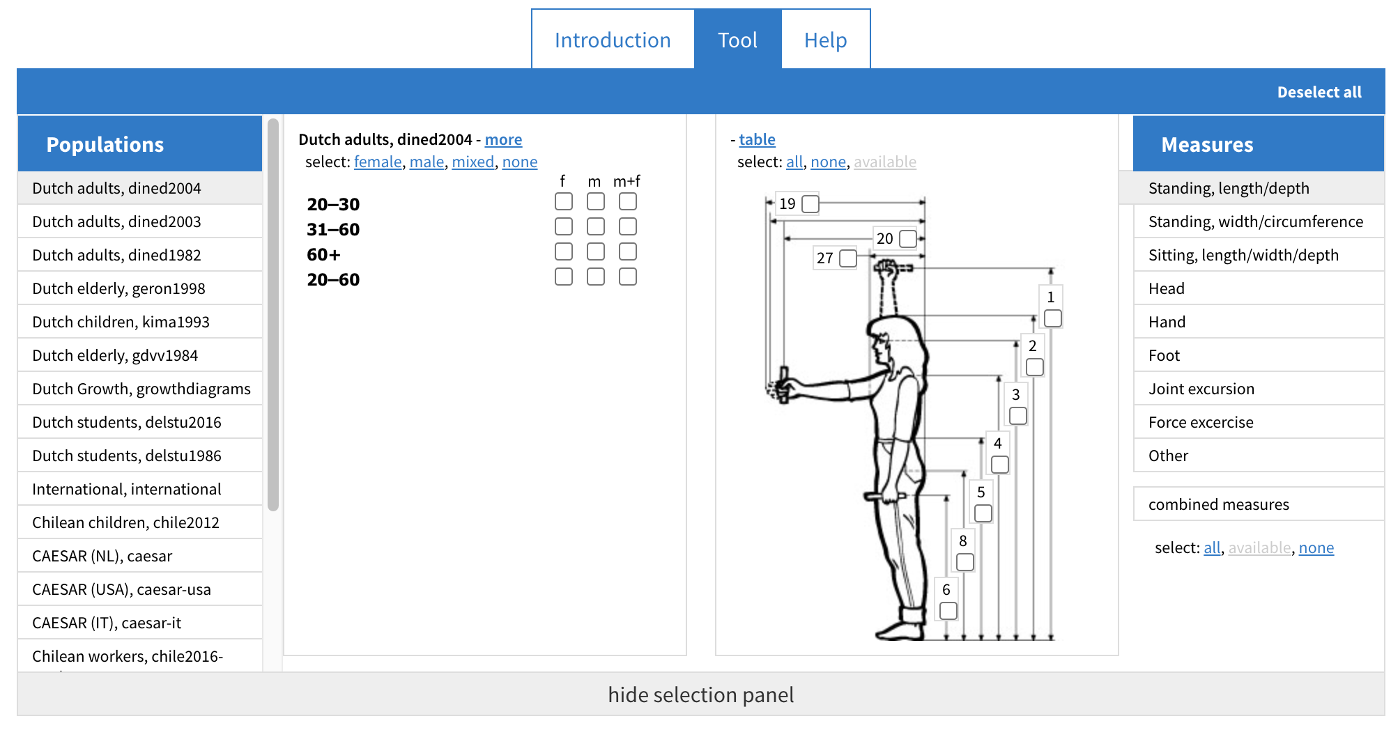 Typically anthropometric data were collected in several positions, the data generated by these postures can provide rich data related to body surface shape. However, the data does not contain a lot of bony landmarks. What is bony landmarks? A bony landmark is any place on the skin surface where the underlying bone is normally close to the surface and easily palpable. Typically anthropometric data were collected in several positions, the data generated by these postures can provide rich data related to body surface shape. However, the data does not contain a lot of bony landmarks. What is bony landmarks? A bony landmark is any place on the skin surface where the underlying bone is normally close to the surface and easily palpable. (SegensMedicalDictionary, 2011) Although most anthropometric data can be easily used in blender’s scaling function to scale every segment of the body, but for scaling the musculoskeletal model, the process is mainly dependent on the data with bony landmarks. In order to make the scaling process more uniform, this project has selected data only with bony landmarks and created a tool in excel to make the scaling process easier. The process of filtering anthropometric data with the bony landmark is described in detail in the subsequent section on scaling musculoskeletal models. • Input: A generic template model of a human body and information on bony landmarks, the spots on the body where bones are close to the surface and easily palpable • Output: The generic template model with adjusted body proportions for a scaled musculoskeletal model based on bony landmarks • Control: Accuracy of anthropometric data used for scaling, efficiency and effectiveness of the excel tool for data filtering and scaling and quality and accuracy of the scaled models • Resource: Anthropometric toolkit, 3D modeling software (such as Blender) and Access to bony landmarks data |
| A4 Scaling process | • Description: Select the target populations, gender and age range. This is followed by the selection of the target segment’s data. This step can be done by referencing the data provided in the template excel tool, or if a more detailed database is available, it can be adjusted in a more complete way. Finally, select the percentile of the target data. Typically, the P5, P50, P95 data are preferable. Once the required data has been selected, it is time to generate the dimensions of the body parts. This step mainly involves entering the selected data into the excel tool, which will then automatically generate the data for each body segment in a graphical way. The final scaling step can be carried out in any modeling software, here it is recommended to use Blender, select the individual body parts and scale them according to the dimensions. 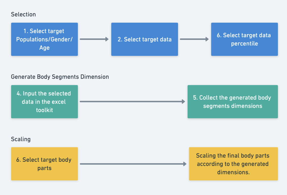 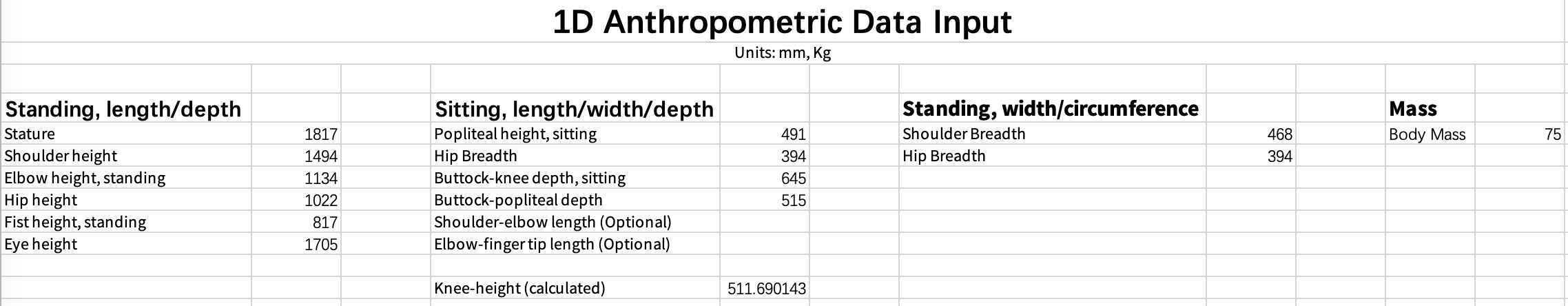 The diagram below shows the dimensions of the generic human body. You can see that for the width of the human body the data is mainly focused on the height and there is less information on the width. This is also due to the issue that the anthropometric data is not comprehensive. The diagram below shows the dimensions of the generic human body. You can see that for the width of the human body the data is mainly focused on the height and there is less information on the width. This is also due to the issue that the anthropometric data is not comprehensive. 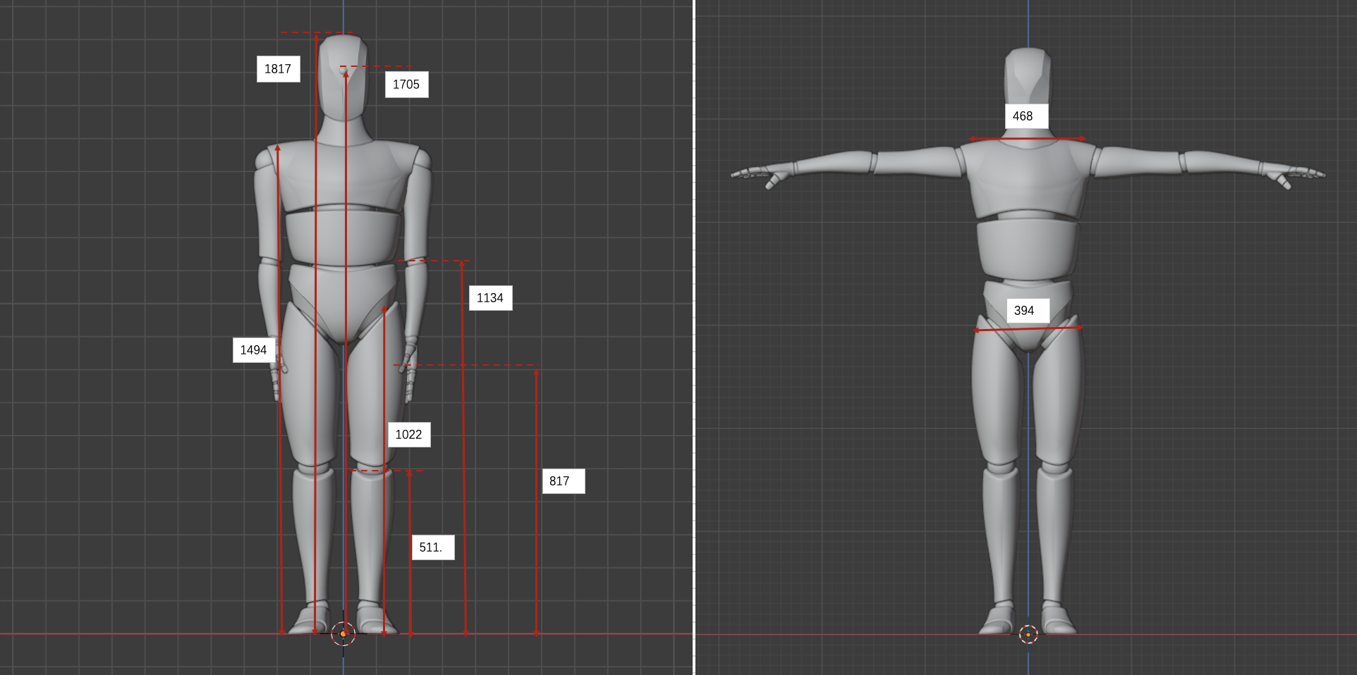 Tutorial 1 - Change body proportion of Body Surface Model • Input: The target population’s data, including gender and age range for the tamplate • Output: A scaled 3D model in Blender (or any other modeling software) with individual body parts adjusted according to the data • Control: Accuracy in selection of target population and segment data and ensuring the model’s dimensions are accurate and correctly represent the chosen anthropometric data • Resource: Anthropometric data from the target population, the excel tool for data processing and graphical representation |
| A5 Change posture and movement of the scaled body surface model | • Description: After obtaining the scaled human body surface model, The Blender armature function is used to give movement to the model. From desktop research, there are several ways to give movement to a virtual human model: Keyframing, Procedural Animation, Physically-Based Animation, Motion Capture, Forward and Inverse Kinematics. For blender, it is easier to use its inverse kinematic function to create human movement, But for Opensim it only uses a motion capture system to create the movement of the human model. One research (Zhou, 2008) summarised the motion tracking technologies into mainly three categories: non-visual, visual-based (e.g. marker and markerless based), or a combination of both. From research, also suggested the Inertial sensor is the most outstanding motion tracking technology so far, with high accuracy and compactness, fewer computation resources needed, and low price. For this project, a markerless tracking solution based on an RGB-D camera is used. Kinect was chosen mainly because it provides good software support, which saves a lot of resources during the development process. It is also very cheap and easy to obtain. • Input: The scaled human body surface model and motion tracking technology, in this case, a markerless tracking solution based on an RGB-D camera (Kinect) • Output: A scaled human body model with the ability to move • Control: Implementation of motion tracking technology and quality and accuracy of the movement • Resource: The scaled human body model, 3D modeling software, motion tracking technology |
| A6 Creating human model movements | • Description: 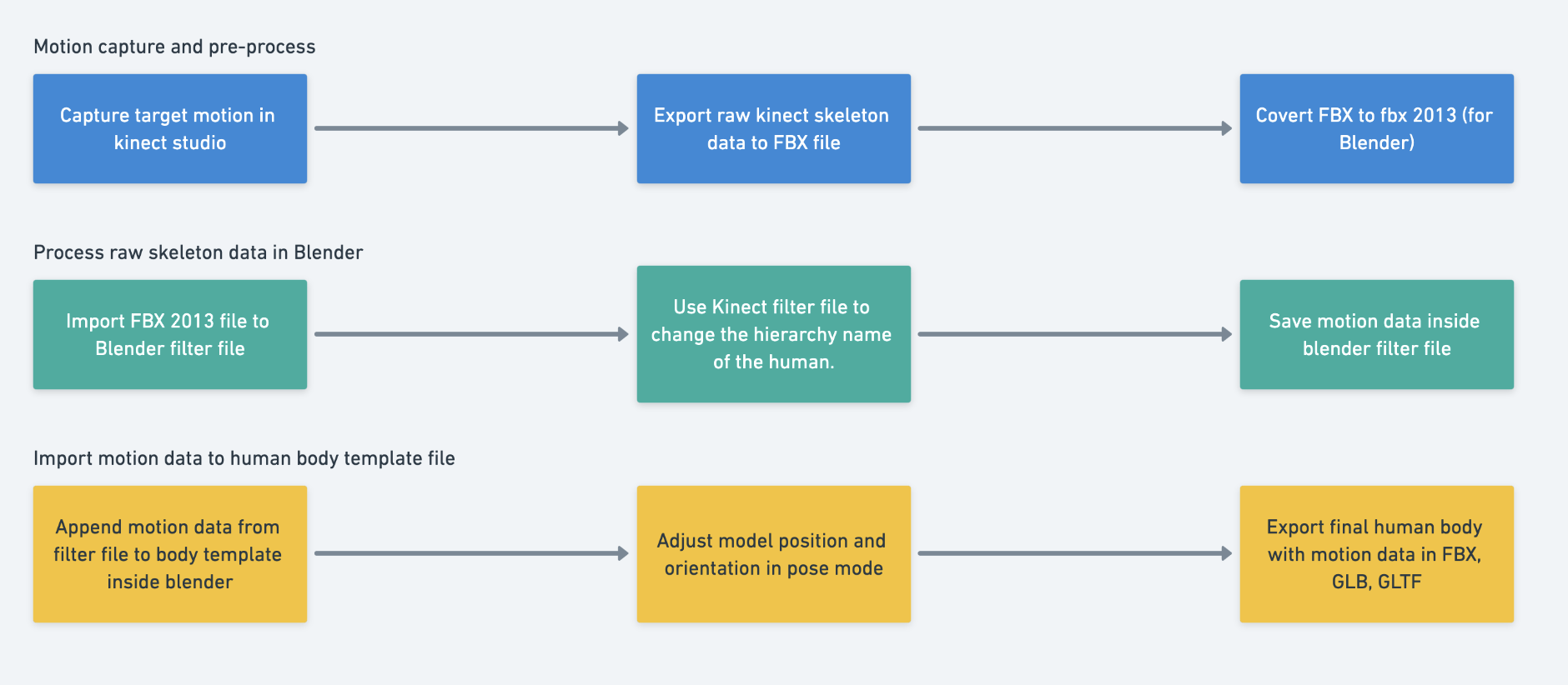 In the first step, the user will first record the subject’s movements using Kinect Studio and then use Kinect Animation Studio to convert the recorded data, resulting in an FBX file. However, the generated FBX file from Kinect Animation Studio is not supported by Blender, so we need to use Adobe FBX Converter to convert the exported FBX to FBX 2o13 format. In the second step, open the Filter file from the toolkit and import the FBX 2013 file generated, then go to the Scripting window in Blender and click on run. The Filter File will automatically adjust the name of the exported skeleton and finally, and save the Filter file. So what does the Filter file do? If you open the unprocessed FBX2013 file directly you will see that all the bones follow the naming convention like SkelXXXX:SkeletonName, where XXXX is a four-digit random number. In the later operations, the general idea of using the raw skeleton data is to “teach blender copy/link data (position rotation) to the target body joints/segments”. With the unique XXXX number from each motion capture session, Blender is not capable of recognizing them, therefore the filter file will remove the random number. Blender supports appending motion data from one file to another, for the third step, we can append the pre-processed data from the filter file to the template body surface model. The template file with two armatures inside. An input armature and a target armature. The input armature has the same skeleton hierarchy by comparing the filter file. The target armature copies/links the motion data from the input armature. We have to append the motion file to the input armature. However, sometimes, if we place the Kinect in a wrong angle or position, the imported animation will have a strange height and angle. The toolkit provides a controller for you to fix this problem, you can select the input armature and enter pose mode, in front of the skeleton, you will see the round shape controller. You can rotate and move the controller to change the entire skeleton of the skeleton. For more detailed operations, try to see the video below. Tutorial 2 - Create movement for Body Surface Model • Input: Recorded subject’s movements using Kinect Studio • Output: The final animation in Blender with the option to correct any anomalies in the animation due to improper Kinect positioning • Control: Accurate motion capture and preprocessing using Kinect Studio and Kinect Animation Studio, nnsuring correct alignment and positioning of Kinect during the motion capture process • Resource: Kinect Studio for motion capture, Adobe FBX Converter to convert the exported FBX to FBX 2013 format and Blender for animation |
Human Musculoskeletal Model
This section will briefly explain how to use Opensim for mulsculoskeletal scaling and Inverse Kinematics. At the end of this part you should have a musculoskeletal model based on anthropometric data and an Opensim motion file based on Kinect raw data. These files can provide a good basis for later biomechanic analysis.
Workflow development
| CONTROL: Accurate and detailed modeling of body structures such as bodies, joints, and muscles, accurate recording and processing of marker data to reflect real human anatomy | ||
| INPUT: Desired human musculoskeletal model or task (e.g., walking, sports performance) | 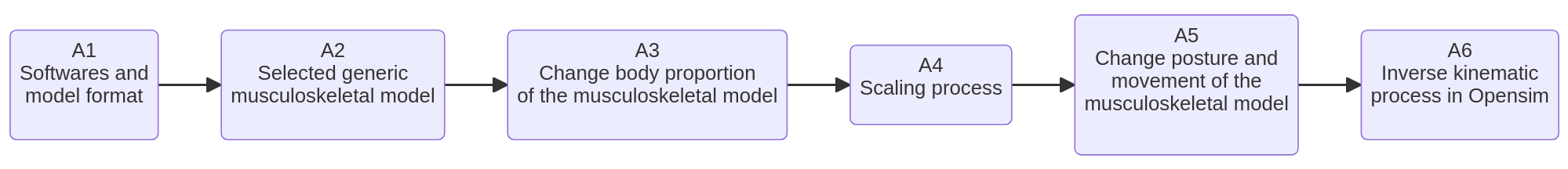 | OUTPUT: A scaled model based on Kinect data |
| RESOURCE: Opensim, Kinect motion capture system,Excel toolkit |
Workflow Building-Blocks
| Acitivities | Overview |
|---|---|
| A1 Softwares and model format | • Description: Opensim was chosen for modeling the human musculoskeletal system. OpenSim is a opensource software that allows a wide range of studies in the neuromusculoskeletal system, it provided a shared platform for accessing the musculoskeletal system. There are many existing models available in the repository ready for use. An Opensim model made from different components can be different according to the different purposes of the simulation, for instance, for simulating human walking, the joint mainly specifies the articulations at the pelvis, hip, knee, and ankle joints, etc. An OpenSim model typically in .OSIM suffix can be used to represent body structures such as bodies, joints, and muscles. Thanks to the graphical interface, the human body can be easily modeled in detail through it, if you have knowledge of anatomy and biomechanics. • Input: Desired human musculoskeletal model or task (e.g., walking, sports performance) • Output: Accurate simulation of desired human activities, sports performances, surgical procedures, joint loads, etc. • Control: Accurate and detailed modeling of body structures such as bodies, joints, and muscles • Resource: Opensim, Opensim repository and Knowledge resources in anatomy and biomechanics |
| A2 Selected generic musculoskeletal model | • Description: As modeling human musculoskeletal models require a lot of knowledge of anatomy, I did not choose to model by myself but rather chose open-source models that are already in the Opensim repository. The chosen models focus on the whole body, not in particular body segments, and here I found two models which are available. The first one was provided by Andrea Menegolo. https://simtk.org/projects/ulb_project. The second one was provided by Apoorva Rajagopal. https://simtk.org/projects/full_body The examples in this document were carried out using models provided by Apoorva Rajagopal. • Input: Specific requirements or objectives for the simulation and Opensim repository • Output: Detailed and functional Opensim model of the human musculoskeletal system (.OSIM file). • Control: Accurate and detailed representation of human body structures, including bodies, joints, and muscles. • Resource: Opensim |
| A3 Change body proportion of the musculoskeletal model | • Description: In Opensim, the process of modifies the anthropometric data of a model is called scaling, Scaling is typically performed by comparing experimental marker data to virtual markers placed on a model, In OpenSim, the scaling step adjusts both the mass properties, as well as the dimensions of the body segments. In order to run a scaling process, three input is required: - The first is a Generic model provided by Opensim, depends on the different research purposes, the musculoskeletal structures can vary from each model, the picture here shows a model designed for gait analysis, so we can see it more focused on lower limb part. - The second input file is the Marker files in trc suffix, it is usually several seconds of data with the subject posed in a static position. - The last file required for scaling is the setup file for the Scale Tool, a file to teach Opensim how to compare the virtual markers to match experimental marker locations captured from the subject. With these three files, the anthropometry of the generic model will match the anthropometry of the particular subject. 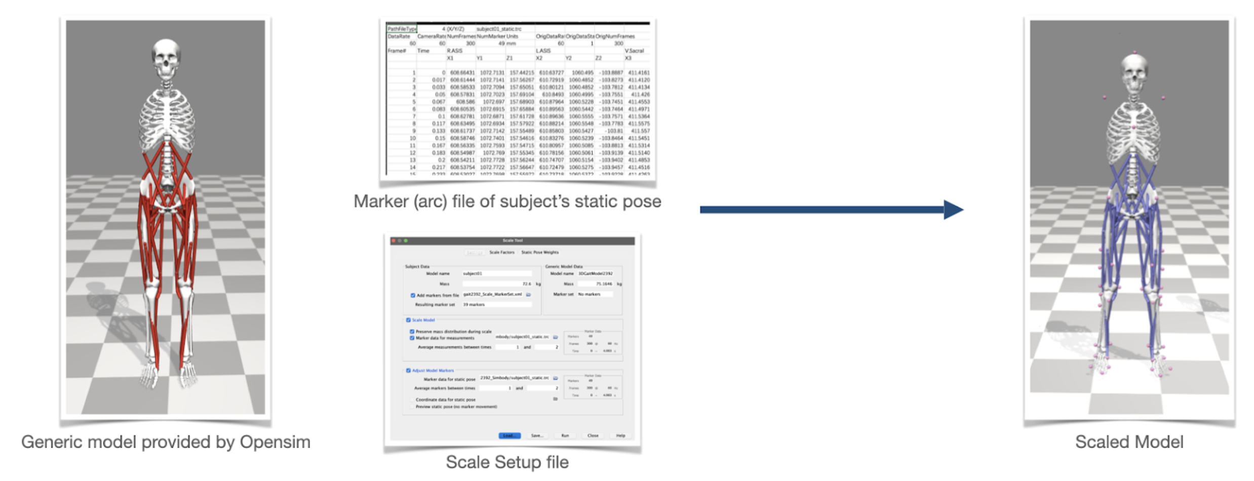 About the three inputs of the scaling process: a generic model, a marker file, and a scale setup file. As mentioned, to obtain a marker file, the usual method is to use a motion capture device to capture the virtual markers placed in a real human. So we will face some difficulties to get a marker file from 1D anthropometry data. Therefore knowing how the scaling process works are very important for figuring out a way to generate a marker file from 1D anthropometry data. When performing the scaling process, Opensim will try to get the coordinates of each marker in real life and then compare these markers with the virtual markers on the virtual human model. Assuming that there are A1 and A2 markers in real space and B1 and B2 markers in virtual space, Opensim will calculate the distance M1 from A1 to A2 and the distance E1 between B1 and B2 and divide E1 and M1 to obtain the scale factor S1. If A1 and A2 are placed on the right leg bone, for example in the picture A1=R.ASIS, A2=R.Knee. Lat. Opensim will then scale the corresponding leg bone according to the scale factor S1. If the marker of the left leg bone is also captured, the corresponding left leg bone will also have a scale factor S2. 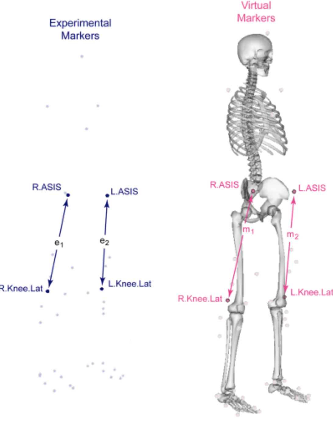 There are three requirements for placing the markers: 1. at least place three markers to track the position and orientation of a particular body segment. 2. better to place markers in anatomical locations with the least skin and muscle movement. 3. reference markers set provided by Opensim can be used. For the scaling process, requirements 1 and 3 are not important for now, the second requirement is crucial for adopting the 1D anthropometric data in the scaling process. Where are the anatomical locations of the human body? Or in another term bony landmarks. The bony landmark is any place on the skin surface where the underlying bone is normally close to the surface and easily palpable. The picture below illustrates the bony landmarks of the human body. 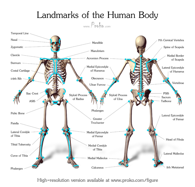 For OpenSim, the bony landmarks are the most reliable markers for the scaling process. However, in many studies where anthropometric data were collected, most of the data collected did not contain a definition of bony landmark, so we needed to review the definitions in detail and filter out the data that contained bony landmarks to help Opensim perform scaling operations. In this document, I used the dutch adults’ data from Dined as an example to show the filtering process. 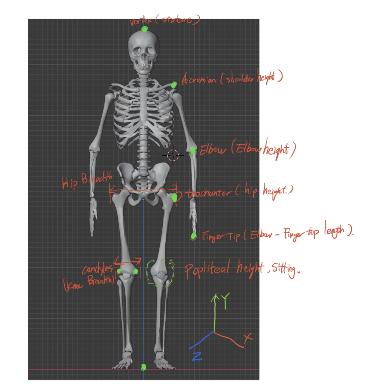 As you can see from the picture above, the selected bony landmarks were marked out in green. They are Vertex from Stature, Acromion from Shoulder Height, Elbow from elbow height, Trochanter from hip height, Fingertip from the elbow-fingertip length, Knee height from popliteal height sitting. These markers can give a basic scale of the upper limb and lower limb. As anthropometric data is not originally collected to provide detailed data for anatomy, we are missing many details such as ankles, the width of the body segments, etc. But for ergonomics analysis, these data can provide a basis for anthropometric scaling in Opensim. • Input: Generic model provided by Opensim • Output: A scaled Opensim model whose anthropometry matches that of the specific subject • Control: Accurate recording and processing of marker data to reflect real human anatomy • Resource: Opensim, Motion capture device |
| A4 Scaling process | • Description: As anthropometric scaling in Opensim is a tedious process, not only about creating marker files but also needs to set up the correct virtual markers to be placed on the virtual human model, as well as the scaling configuration files. These files make the scaling operations incredibly cumbersome for the average user, so a simple toolkit has been created that allows users to quickly perform scaling operations when using the Dined anthropometric database. However, there are limitations to this toolkit; if some data is missing/not found from the anthropometric database, or if the data is defined differently, then the scaling process will not work and need to be redesigned from the beginning. 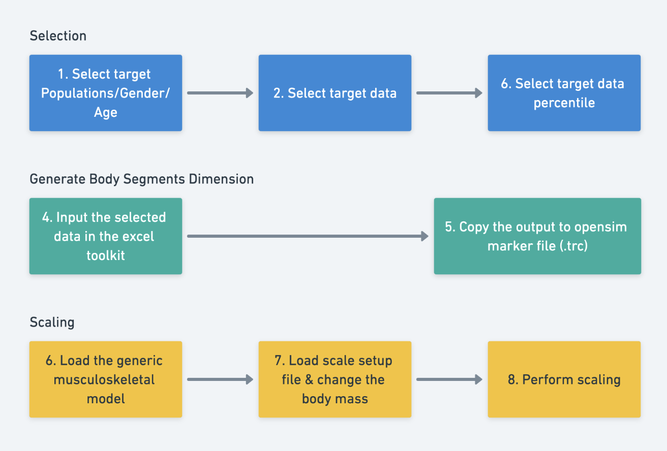 The diagram above shows the simple process of using Toolkit. The first step is the same as scaling a human surface model, selecting the target population, gender, age, data, and percentile. Then the data is entered into the excel toolkit, which is “anthropometry2trc.xlsx” In this Excel file, the user can enter the specified anthropometric data and the file will automatically generate marker parameters. The generated marker parameters then need to be copied into the ScalefakeMarkerFile.trc. 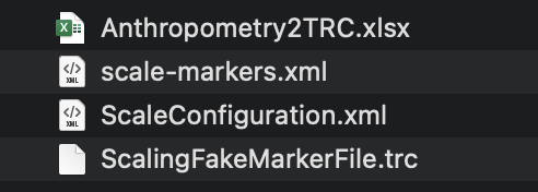 “scale-markers.xml” and “ScaleConfiguration.xml” files are pre-defined templates and do not need to be modified. The user only needs to load the generic model “FullBody-Template.osim” and open the scale function in Opensim & load ScaleConfiguration.xml, then change the body mass of the target population. Finally, perform scaling. For a better understanding of this process, please see the video below. Tutorial 3 - Change body proportion of musculoskeletal model in Opensim • Input: Target population, gender, age, data, and percentile selections, anthropometric data entered into the Excel toolkit anthropometry2trc.xlsx, generic model FullBody-Template.osim provided by Opensim, scaling configuration files: scale-markers.xml and ScaleConfiguration.xml • Output: Scaled human model in Opensim, whose body proportions match the specified anthropometric data. • Control: Proper use of the Excel toolkit to generate marker parameters and correct use of the scaling function in Opensim, including loading the right files and modifying body mass. • Resource: Opensim, Excel toolkit anthropometry2trc.xlsx |
| A5 Change posture and movement of the musculoskeletal model | • Description: In Opensim, the function for creating human movements is called Inverse Kinematics (IK). This tool uses experimental data from each time period to create coherent human movements by positioning the model in the pose that ‘best matches’ the experimental Marker and coordinating data for that time period. The final output of the IK process is an MOT file, meaning motion files, the motion can be used for another OpenSim model, with the same marker set. Opensim’s IK tool will use a set of algorithms to obtain the pose with the least error, and we need to assign different weights to the Marker in Opensim’s IK configuration files to help Opensim to perform the calculations. In general, to perform an IK activity we need the following inputs: a generic full-body musculoskeletal model of the human. A marker file with a .trc suffix, which is usually a set of markers obtained from a motion capture system (sample like the file in the scaling process). Finally, the configuration file which weights each marker. With these three files, we can perform Inverse Kinematics operations on the generic musculoskeletal model in Opensim. But since Kinect is a markerless motion capture system, we do not have access to the coordinates of the real Marker in the human body, and it seems that we cannot perform Inverse Kinematics operations. However, this problem can be solved by reviewing the raw Kinect data and it is not hard to see that the raw data defines the change in position of each joint in space. In the diagram below, there are 25 body joints defined. So if we look at these joints as real markers which are placed on the body, we can perform IK activities through Opensim. (which means place OpenSim markers inside the musculoskeletal model) As can be expected, this approach is not 100% anatomically correct, but it can provide us with basic human movement data. In addition, our scaling model is derived from anthropometric data, so that the accuracy of scaling process of the human body during the IK activity is not very important to us. 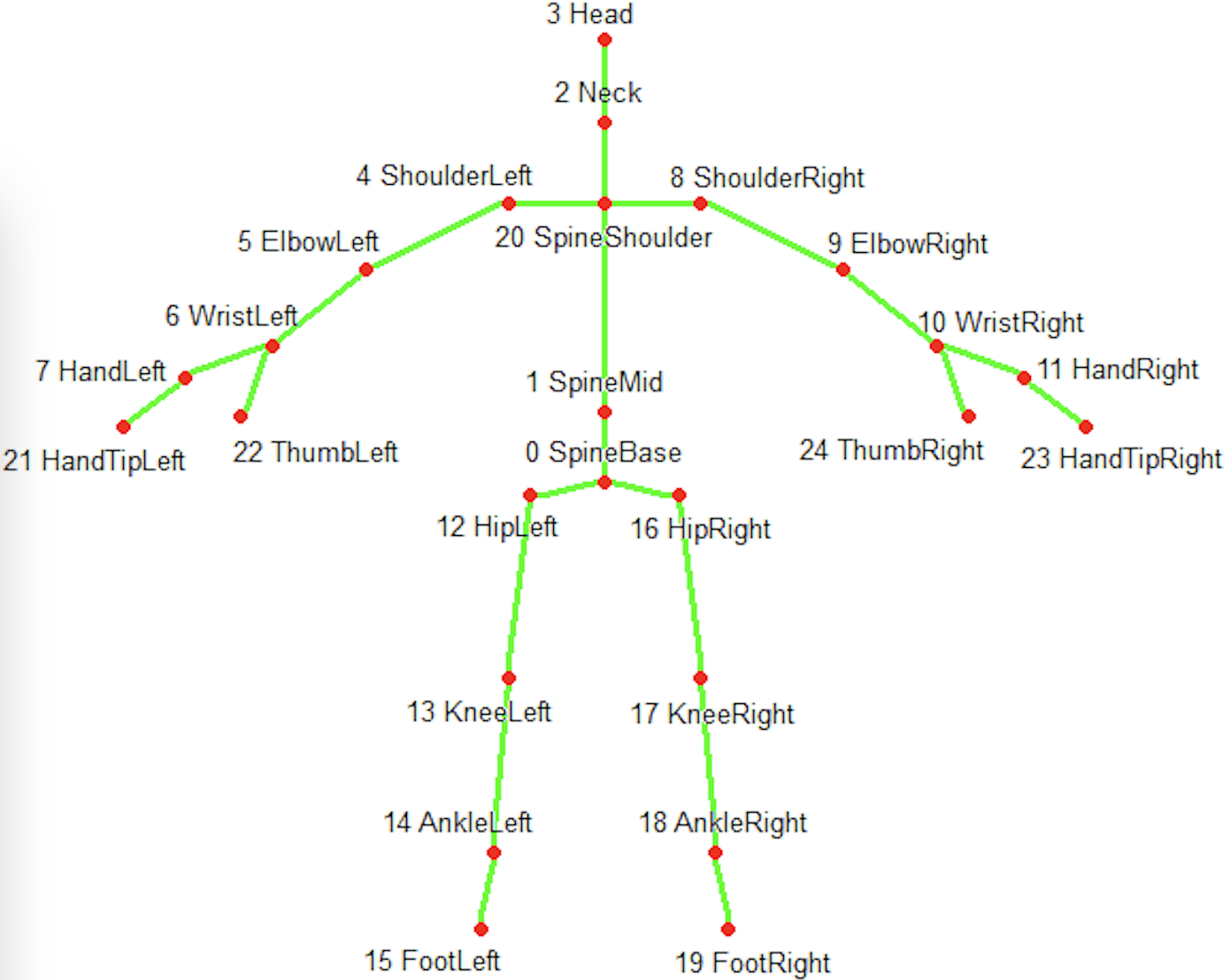 However, the position of the Kinect joints cannot be used directly in Opensim, because the coordinate system of Kinect is different from Opensim. For example, the Kinect coordinates are centered on the Kinect camera, whereas the Opensim coordinates can be located in the center of both sides hips as the origin X and the YZ value of the Ankle on either side as the origin YZ value. In addition, we need to rotate the Kinect coordinate system by -90 degrees along the Y-axis to be the same as Opensim. Finally, the Kinect coordinate system has different units and you will need to calibrate it to get the units in real space, as Inverse Kinematics does not have very strong requirements for the dimension of the model (more about joints’ rotation), here you can simply multiply all the coordinates by 1000. you can visit these two links for more information: - RECONSTRUCT HUMAN BODY MOTION IN OPENSIM WITH THE KINECT XBOX ONE - How can I Convert Kinect rgb and depth images to real world coordinate xyz? 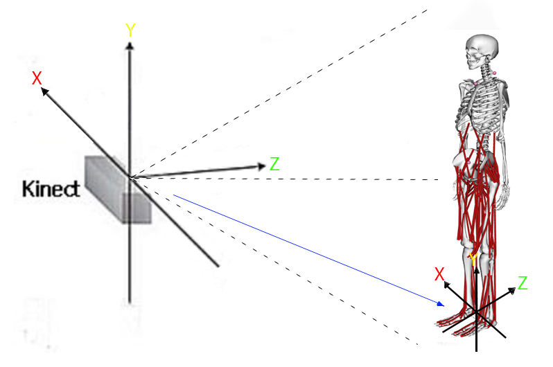 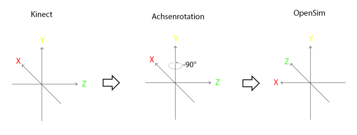 • Input: A generic full-body musculoskeletal model of the human, motion capture system, raw Kinect data, • Output: Accurate simulation of desired human activities. • Control: Accurate and detailed modeling of body structures such as bodies, joints, and muscles, correct use of the Inverse Kinematics (IK) tool in Opensim to generate coherent human movements. • Resource: Opensim, Kinect motion capture system. |
| A6 Inverse kinematic process in Opensim | • Description: 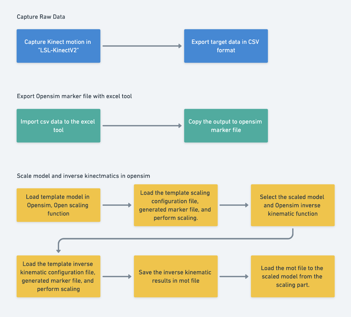 The diagram above shows a basic Inverse Kinematic process, divided into three main steps, the first step is to acquire the Kinect raw data, the second step is to export the Kinect raw data to an Opensim Marker (.trc) file. The final step is to perform IK operations in Opensim. In the first step, we will use a software called “LSL-KinectV2”, which is an open-source motion capture software that can store Kinect data in a CSV file. If there is other software that can export Kinect raw data, feel free to use it. In the second step, we need to use the excel tool provided to convert the acquired Kinect raw data into a marker file that Opensim can recognize. The main purpose of the excel tool is to convert the coordinate system of the Kinect data, and make an output that Opensim can recognize. 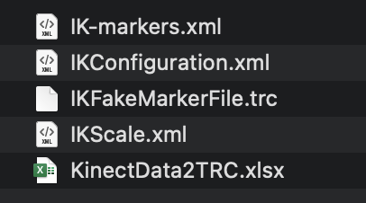 Finally, once we have the converted Kinect data in the .trc file, we can perform an inverse kinematic operation; the IK operation can generate a Motion file (.mot) which can be loaded into any size musculoskeletal model for biomechanical analysis. However, it is important to note that in order to make the IK results more accurate, we need to perform another scaling operation based on the Kinect data before the IK operation. First, load the generic human model and then turn on the scaling function. Load the IKScale.xml file, modify the mass data and click on the “run” button. After getting the scaled model, we can select the scaled model and turn on the inverse kinematic function, then load the IKConfiguration.xml file. Click on Run, then Opensim will start the IK operation. When the IK process is over you will find a motion file in the file path you assigned before. Before proceeding to the next step about analysis, first, the model previously scaled according to anthropometric data needs to be loaded and then the motion file needs to be loaded onto the scaled model too. Tutorial 4 - Create movement for musculoskeletal model • Input: Kinect raw data obtained using software such as LSL-KinectV2 or any other software capable of exporting Kinect raw data. Generic human model in Opensim. IKScale.xml file for scaling operation. IKConfiguration.xml file for Inverse Kinematics operation. • Output: An Opensim Marker (.trc) file, which is a conversion of Kinect raw data. Motion file (.mot) generated by the Inverse Kinematics operation, which can be used for biomechanical analysis on any sized musculoskeletal model. A scaled model based on Kinect data. • Control: Successful performance of the Inverse Kinematics operation in Opensim using the IKConfiguration.xml file. • Resource: Opensim, LSL-KinectV2 software or other software capable of exporting Kinect raw data. |
Joint Lab Works
Remote movements analysis experiment
Colleagues from the University of Belgrade also have Kinect sensors in their lab, so we planned a small experiment to explore the possibilities of remote analysis. The procedure was for the colleagues from Belgrade to record a piece of Kinect motion data and send it to the lab in Milan. The students in Milan tried to reproduce the action in Opensim.
The data sent from Belgrade was stored in Matlab files, so we designed a script to convert the MATLAB data to CSV data, then flowed exactly the designed workflow about inverse kinematics. Worth mentioning that the data in Matlab followed a common hierarchy of Kinect skeleton data, with a total of 21 joints defined. But without the thumb and hand tip data, because they are not reliable in Kinect, therefore in the Opensim Scale&IK configuration file we need to delete relevant information about thumb and hand tip data.
The end result of the experiment was a general success, but the Inverse Kinematic results were rather odd as the data eventually obtained was not accurate due to the complex environment during the preliminary data collection. Therefore we have also summarised some key points when using Kinect for data collection: 1. For getting more reliable data, we can measure the subject’s pelvis height and place the Kinect at the same height. 2. Keep the Kinect parallel to the ground. 3. Make sure the subject always moves in the area that Kinect can detect. 4. Record FPS data
Automated anthropometric data modification in VR
There are some pain points in the current workflow. First, the current workflow of changing anthropometry of the virtual human is lacking automation, users need to record the anthropometry data to the toolkit and then manually do the scaling process. Second, with the current workflow, users can only use the defined human template, after the VR scene is running, we can not change the anthropometry data of the human model template.
The students from France have explored modeling in VR and from their work we can see there are good opportunities to optimize this project. The work made by Grenoble showed the possibility to link anthropometry data with a 3D model. Therefore the workflow can be fully automated. With the capability to modify models in VR, we can dynamically change the anthropometry of each body segment in real-time, rather than using a predefined human model template.
Future works
Hand Tracking
As professor Colombo says, most production activities take place with the human hand, and Kinect does not have the ability to track the hand, so we need to involve other gesture tracking devices, such as the Oculus Quest. It is worth noting that infrared sensors are used in many VR devices to enable positioning of the VR headset, and the Kinect also uses infrared sensors, which can put the two devices in conflict. For hand tracking, it is also not recommended to use Leap Motion for tracking as it also uses IR sensors. Therefore, a purely visual solution for hand tracking (Oculus Quest) or an inertial sensor-based solution is recommended.
Improve the accuracy of scaling results
The current scaling process based on 1D anthropometric data can provide a very basic model for ergonomic testing, but data of some important joints are still missing. The latest anthropometric data collection has introduced 3D scanning technology and we can expect that the data based on 3D scanning will be more comprehensive. Therefore, it is suggested to pay attention to this technology.
Improve the accuracy of human movement results
There are limitations to Kinect tracking, with a significant quality drop of body tracking results when the subjects perform a 360-degree rotation. The solution could be by placing multiple Kinects in different angles. As mentioned before, the Kinect is based on an infrared sensor and if the VR monitor used also uses an infrared sensor, there will be a conflict for them. Here it is recommended to use an inertial sensor-based solution such as Xsens, or the open-source solution Chordata, to improve the motion capture quality and avoid sensor conflicts.
References
-
Mochimaru, M. (2017). Digital Human Models for Human-Centered Design. Journal of Robotics and Mechatronics, 29(5), 783–789. https://doi.org/10.20965/jrm.2017.p0783
-
Mochimaru, M. (2017). Digital Human Models for Human-Centered Design. Journal of Robotics and Mechatronics, 29(5), 783–789. https://doi.org/10.20965/jrm.2017.p0783
-
Segen’s Medical Dictionary. (2011). Bony landmark definition of bony landmark by Medical dictionary. https://medical-dictionary.thefreedictionary.com/bony+landmark
-
Zhou, H., & Hu, H. (2008). Human motion tracking for rehabilitation-A survey. Biomedical Signal Processing and Control, 3(1), 1–18. https://doi.org/10.1016/j.bspc.2007.09.001