Technological Cell - PT-DT Interaction
The main idea for this step of the project was to create an interaction between the Physical and Digital Twin. In doing so, our main product was a Digital Shadow.
General workflow
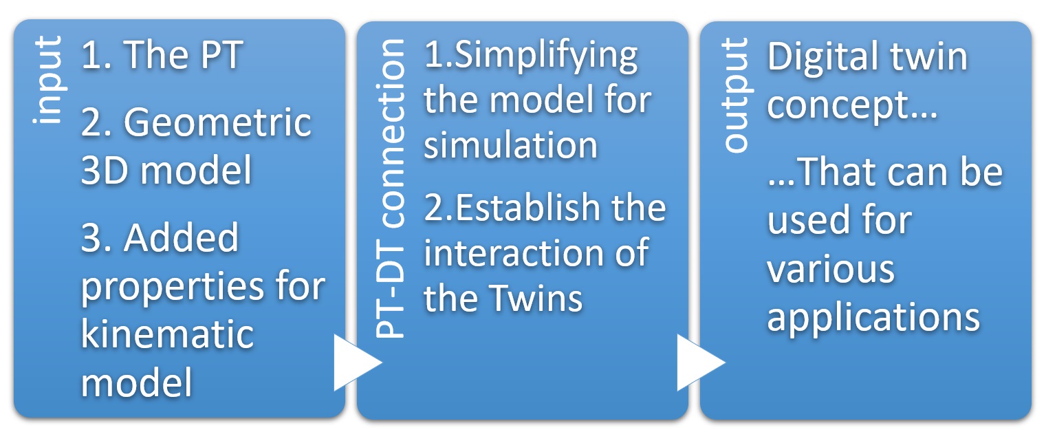
The inputs were the Physical twin and the 3D model made based on it, that with added properties was made into a kinematic model. In this step we simplified the model for simulation and established a connection between the Twins. As the output we got a concept of a Digital Shadow.
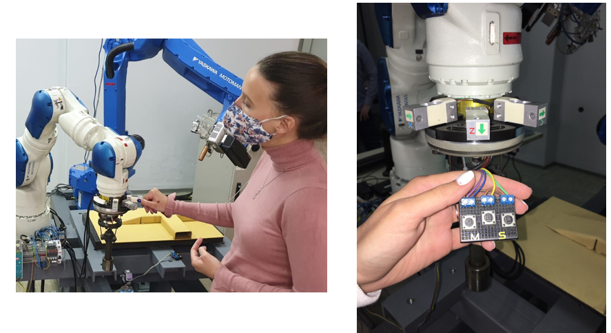
Specific use case workflow
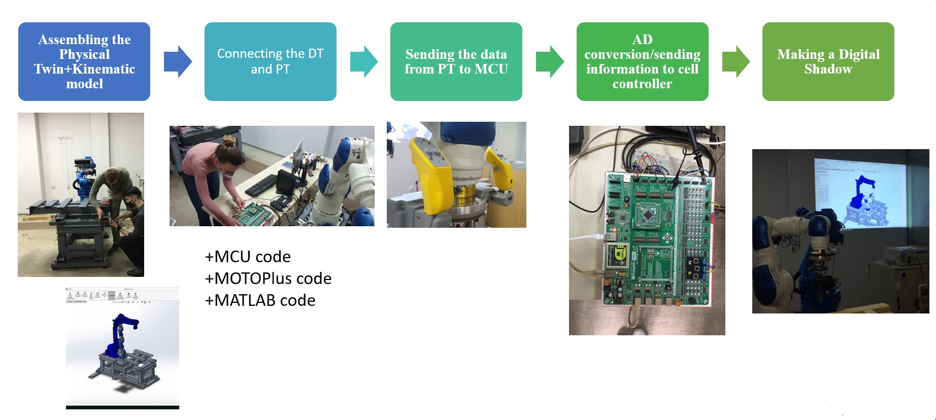
So to better elaborate, our main workflow consisted of actually assembling the PT and making the kinematic model that we used as inputs. Then with them we needed to connect all the parts of the PT with each other as well as the PT with the DT, for which we used various codes. When everything was connected and the interaction enabled making of the Digital Shadow was possible. The Physical robot was programmed by Programming by Demonstration, so by us without a single line of code with the help of a haptic tactile device that is shown in the middle picture of the specific use case workflow. That data is further sent to the MCU for AD conversion and it is made into strings ready further use. Parallel to this information is also sent to a separate PC for Digital Shadow visualization, so when the PT moves the Digital Shadow moves along.
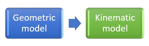
The main activities in this step of the project
We needed to transform a geometric model into a kinematic one. We simplified the model for the simulation, meaning that the assembly of the base that consisted of many parts was saved as one part and the links of the robots we added one by one with the appropriate mates and axis.
Geometric model of the technological cell
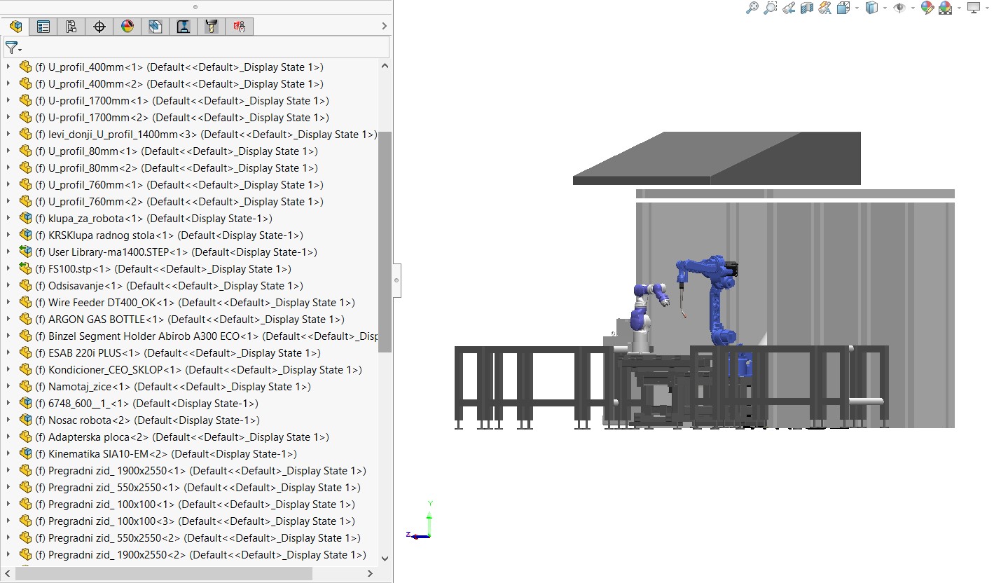
In the picture it is clear there were many parts in the assembly, and in the simplified model only the amount necessary for the functionality of the Digital Twin. This greatly affects the performance and speed of the Digital Twin.
Simplified model
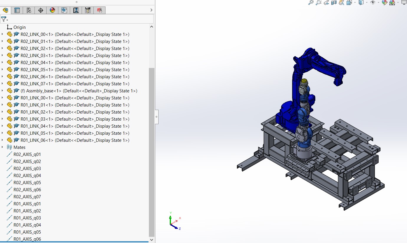
The axes and mates were added based on the convention that was presented on the lectures. The links were named in the following manner, for example for the first link of the first robot R01, and than the number of the link LINK_01.
The next step was to enable the communication between the twins, so the twins would be able to affect one another. For this to be possible we needed to enable the circular exchange of data/information. Raw data sent from the PT and information sent from the MCU after AD conversion. Without this exchange the whole concept wouldn’t have sense.
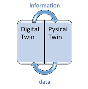
The main task is, as already stated the interaction. There are two key forms PT-DT and DT-PT, thus meaning that two communication channels are needed. The first one is carrying raw data from the physical space to the virtual space, and the second one processed data/information.
In addition to them a local feedback data exchange is needed for control, as for example a communication protocol that controls the functionality of the Ethernet communication channel.
Our goal for this project was Robot Programming. This task is not at all simple, but on the contrary it is a really complex and possibly dangerous task. Even small mistakes can lead to the damage of the equipment or even harm or even fatally injure the workers. This job has many steps and as learned from the lectures some of them are>We learned from the lectures that robot programming consists of:
- Task setting and planning
- Motion specification and optimization (cycle time analysis and other process analytics)
- Coding (creating robot job task code)
- Simulation / Visualization and verification
- Generalization and learning
- Knowledge/skills distribution to other robots…
Robot programming can be done in various ways.
- Online, via Robotic Teach pendant
- Offline using scripts in robot programming languages
- Offline using simulation software
- or as we want to do it by Programming by Demonstration
Programming by Demonstration/PbD
This is a very useful way to program a robot because it allows us to do so, which as we said is difficult, without any lines of code. This allows humans to share their skills with robots and lend their flexibility to them. The economy based on small batches demands frequent robot programming and great flexibility that the robots do not posses on their own. This is where humans come in and act like a teacher to a robot student. This eradicates the possibility of errors due to coding and doesn’t involve complex mathematics that is needed to program even the simplest tasks. This means that this is a hybrid system, that involves humans and robots alike.

Robotic Use Case DT is very complex. Especially complex when it comes to communication, where the required frequency is immediate real time or event driven.
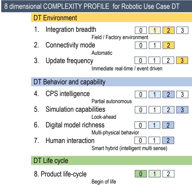
As mentioned, two key forms of interaction: physical twin - digital twin (PT-DT) and digital twin - physical twin (DT-PT) through a specific activity relevant to the robotic process. Both ways of communication allow specific activities, that can be used for already mentioned PbD (Programming by Demonstration), where we can record and save the coordinates that the physical robot makes in reality in the virtual space and use them later on, otherwise they would stay unknown to us. (The robot arm can be moved by sensors of pressure, by hand, in any direction we see fit). The reverse direction, from DT to PT can be used for XR PbD, where we can move the robot in virtual space by the haptic device with VR equipment, ensuring that any possible collision is avoided, as well as totally eradicating the safety risks for the workers, and also allowing optimization of the recorded movement. That verified and optimized movement can then be sent to the PT. The two main blocks are the Digital Twin and the Physical Twin.
Digital Twin
Digital twin consists of next elements:
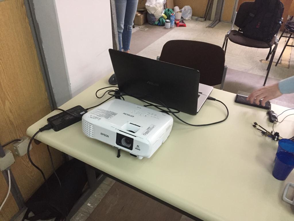
- Separate PC for working with SW API, used for graphic visualization of the model
- Projector – which in this step of the project is used in place of the HMD that will be implemented in the next step, it is used for monitoring of the Digital Shadow
Physical Twin
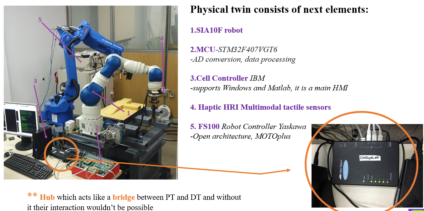
Physical Twin consists of:
- SIA10F robot
- MCU that does the AD conversion and data processing
- Cell controller that supports Windows and Matlab
- Haptic tactile sensors from CMSysLab
- Robot controller FS100
The bridge between them is a HUB device that helps connects all of the parts
Physical Twin Subsystems
-
SIA10F
This is a 7 degrees o freedom redundant robot with the main characteristics of 10 kg payload, very high speed, and open architecture which is a crucial one for it’s use in our project.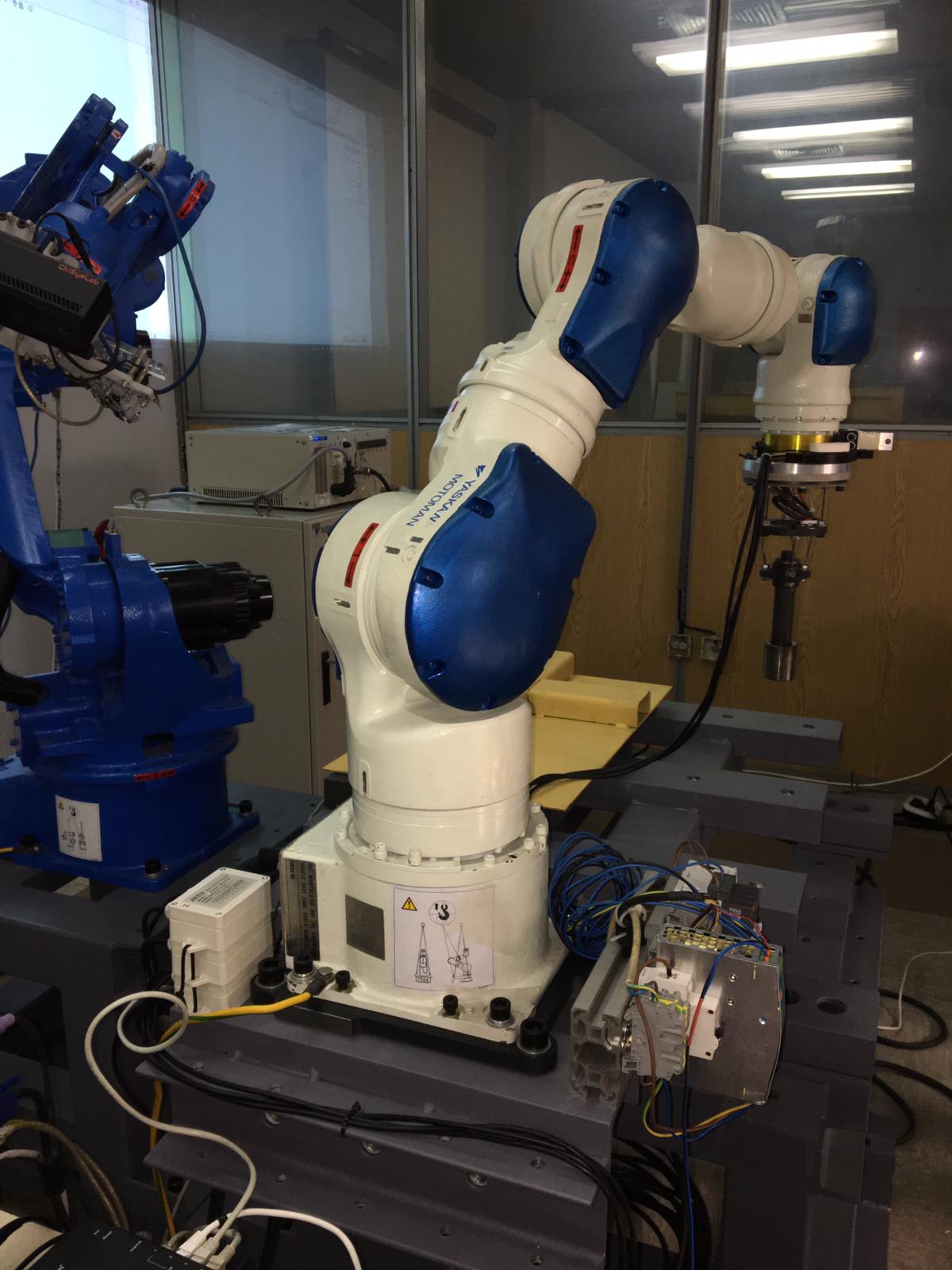
-
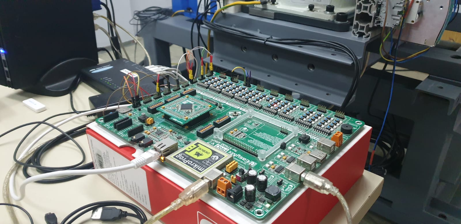
MCU
We used EasyPicV7 and MCU STM32F407VGT6 produced by Mikroelektronika. MCU has following characteristic:- Architecture – ARM 32bit
- Communication speed: max
- 168 MHz (we use 150MHz)
- 1024Kb MCU memory -Dedicated strain-gauge conditioners
-
Cell controller
Cell contoller is connected to the MCU via UART, and all the other subsystems of via Ethernet. It supports Windows and Matlab. And is where we can run the lines of code that we need.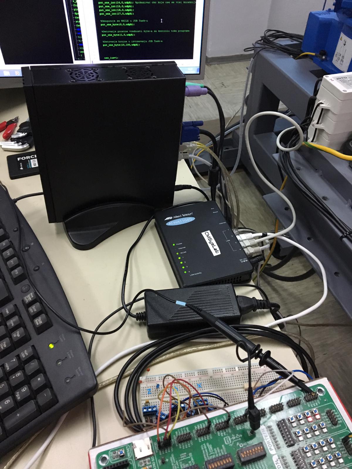
-
CMSysLab Haptic HRI Multimodal tactile sensors
For data streaming haptic tactile sensors that consist out of strain gauges with Wheatstone bridge are used. When we apply force in one of the Cartesian coordinates direction the strain in material occurs which leads to material deformation and change in resistance, that leads to voltage change and after the amplification of that signal (because the change in voltage is of small value) the MCU does AD conversion. A small HMI with three buttons allows us to enable the movement, record the trajectory or to adjust the sensitivity. They allow us to guide the robot in a desired trajectory by simply touching the haptic tactile device.
-
FS100
The FS100 is a robot controller for SIA robot and his key features for us is the open architecture that allows customization in for example C#.
Key features of the FS100 unit:
- Open communication (Based on IBM PC compatible hardware platform)
- Multitasking
- Advanced Robot Motion Unit (ARM)
- Machine safety (MSU)
Infrastructure and coding that we need to achieve our goal
For our task it is necessary to develop inside of Open Architecture Robot Control OARC, and without it we are unable to achieve our main goal of our task, that is physical programing by demonstration in context of real time interaction in direction PT-DT and finally creating Digital Shadow.
Open architecture is a type of computer architecture or software architecture intended to make adding, upgrading, and swapping components easy. Not all robot controllers have it, for an example controller of the other robot in our laboratory, robot welder MA1400, doesn’t have an open architecture. Open architecture robotic control is very important and for us fundamental structure, that allows us to directly communicate with robot in real time situations as well as important intercommunication between modules and peripherals.
How we build our open architecture system
For this purpose, we are going to apply communication between software and hardware with well-defined interfaces between modules.
Open architecture configuration used in our laboratory is made out from 4 systems:
- First one is Robot SIA10F, and its control system unit FS100, made by Yaskawa corporation
- Second one is PIC MCU
- And besides that we have two PCs, one is used as cell controller where MotoPLUS SDK API development software for FS100 controller is installed, and second PC which is used to maintain processes with SW API routines and execute graphical visualization of physical model (Digital Shadow).
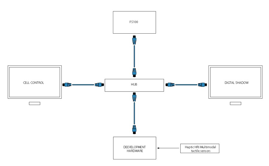
Communication between all of the mentioned modules is made via EtherNet lan cable.
MotoPLUS SDK development software
MotoPLUS SDK is specialized software system/environment, that gives us possibility to approach basic functions of robot control system, its system registers, system parameters, and to alter them in real time. On the basis of this functionality, development and implementation of various executive algorithms is enabled.
Synergy of FS100 and MotoPLUS SDK perform as functionally complementary and complete hardware-software platform which is in development sense absolutely open. Connection among FS100 and MotoPLUS SDK is built using ethernet lan cable.
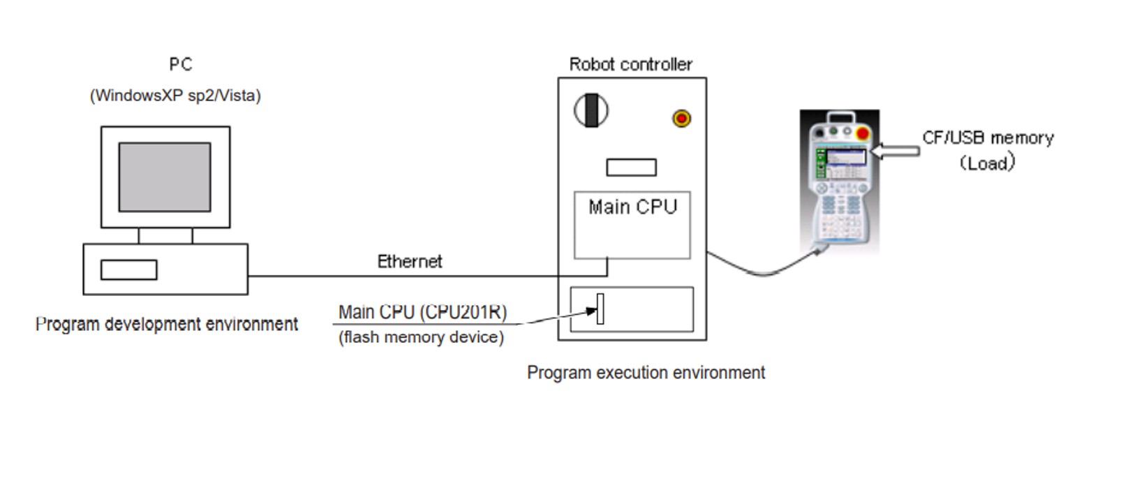
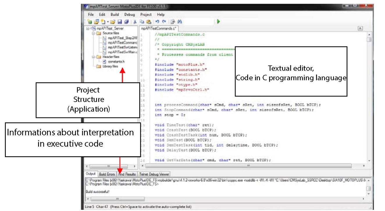
MotoPLUS SDK is installed on PC hardware, where using variety of programing techniques based on C programming language inside development software, user is capable to produce applications in offline mode, that will, in next instance be sent to teach pendant, and finally debugged. Following picture shows MotoPLUS SDK API developing software , and its significant parts of structure. At the left side of the screen we can see project structure (Project tree ) . This lists all source files, header files, and library files that will be compiled when the project is built. Beneath that we can see output information about interpretation in executive code. And of course at the middle we can see project window, where code is written using textual editor.We can develop very wide specter of varieties which differ to our problems.
Main features of MotoPLUS SDK API :
- With C language as the system development language and a wealth of standard libraries, users can create customer specific application programs.
- With the text editor of MotoPlus IDE, users can program off-line
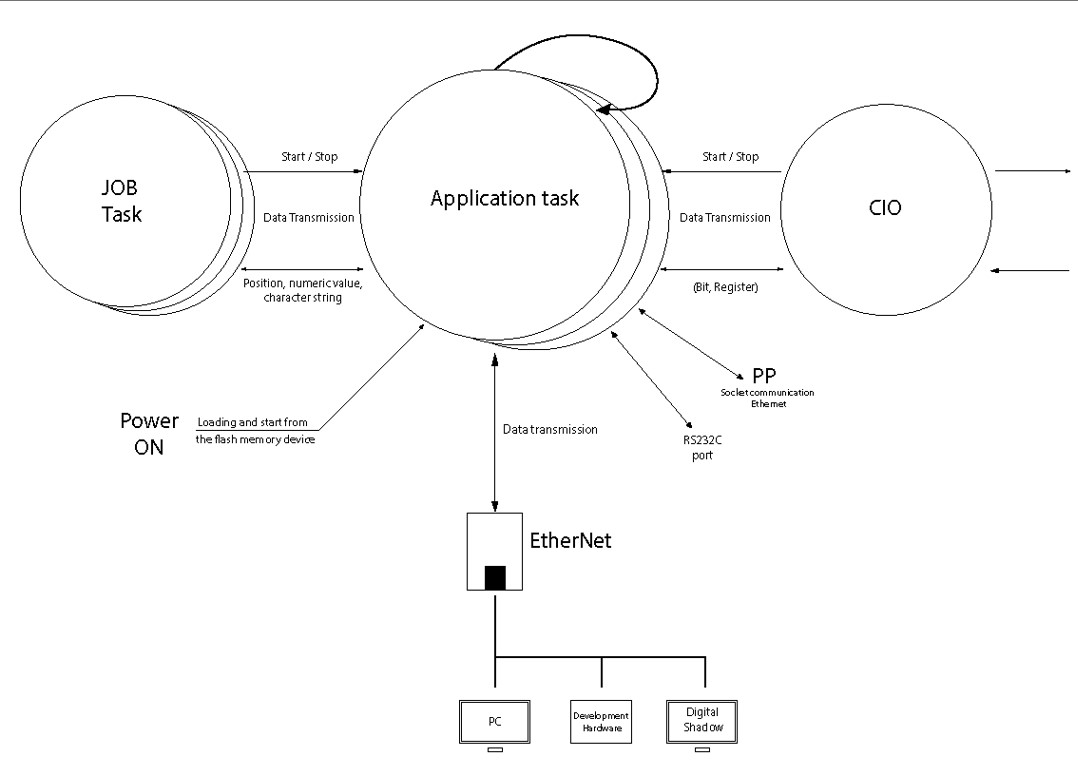
- The created application program runs as a task on the main CPU of the robot controller. Thus, no additional hardware is required.
- With a variety of included APIs (application program interface) to transmit data from/to the job, the Ethernet communication port, and the RS232C serial communication port, etc., users can easily correct the manipulator position and connect the robot to the external PC or sensors.
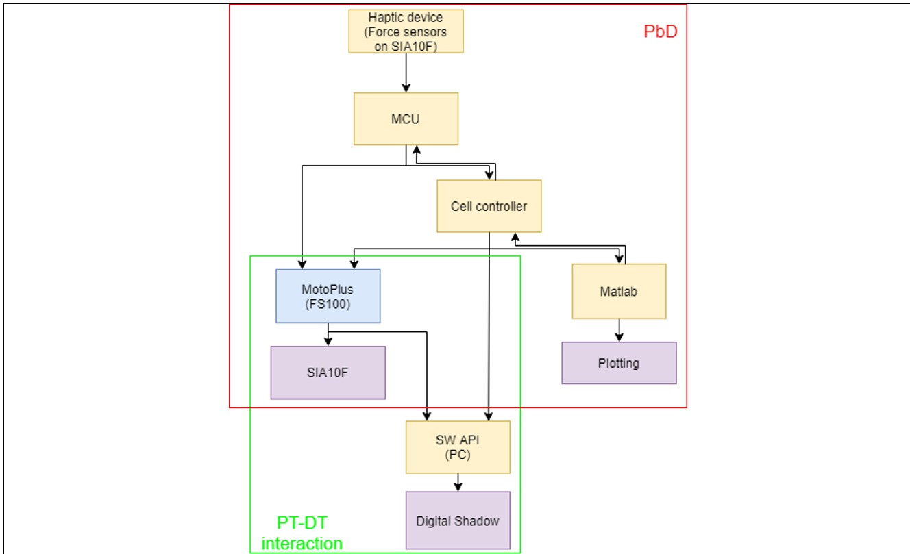
Algorithm for Programing by Demonstration
First we apply force to the force sensors (Haptic device), MCU detects that force, converts it and generate command that calls MotoPlus which moves the robot SIA10F in a wanted direction. By that, we are moving the TCP of the robot in the physical task-space. That is continually taking place, as long as the user (human) sends command for moving from a small HMI that was previously mentioned as a part of the Physical Twin. Center button is used for moving command. As long as MCU sends control commands to the FS100, it sends parallel signal to the cell controller. First part of cell controller output signal is also to the FS100 (it also control directly robot SIA10F trough the FS100). Small HMI, as earlier mentioned, also has the button for recording of movement (it is the right button). If the user uses record command on the small HMI all external, internal coordinates, moment torques and velocities in the joints can be sent to cell controller, where any part of that data can be used. On the cell controller is operating system with Matlab. There data can be visually shown to the user by plotting in Matlab. From there it can be stored or resend to the MCU for reverse movement. Explained so far is representation of PbD (red rectangle in the algorithm), so basically we force the robot to move as we want to, then we can tell him to do the same in both directions. This means that we are the master and the robot is the slave in this interpretation.
Also, there is communication of a cell controller with a SW API through the PC. With the same SW API, controller FS100 is communicating in real-time. It can send packed data about robot trajectory so SW can read it. We can visualize the actual status of a physical robot by updating the angles of it’s joint coordinates in real-time at a reduced sampling rate. That creates a digital shadow. This explained so far is example of Physical twin – digital twin interaction (green rectangle in the algorithm).
ALGORITHM
Parts of the codes used and their explanation
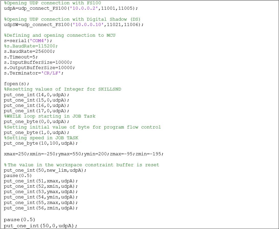
Condition for starting PbD
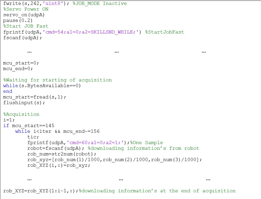
Very important part of controlling the robot is setting the communication between components and subsystems. Before we even start PbD and PT-DT interaction we must interconnect all subsystems with each other and limit our work space. Here is shown the part of the Matlab code from the Cell controller that initialize communication and limits robots work space by a carefully calculated square. Initializing is done by a UDP server that is waiting to receive a message in an infinite loop. From here we can choose different paths, one of them is PbD, as earlier explained. When communication is established, a message parsing and processing routine is called. From there, the classic switch/case function jumps to the routine called by the user. This routine that selects routine from incoming message is processCommand. The absolute user is a human, but the actual users can be a Cell controller and/or digital shadows and/or MCU. The called routine is executed. There are about 60 of them. Of course, message is rejected if it is unsuited. Some routines for an example are: reading coordinates or entering parameters (integer, byte, position variables), then starting JOB TASK and turning on / off servo power, playback routine. After executing the demanded routine, feedback can be sent to the entire controller in the form of loaded coordinates and the current TCP position. MotoPlus routine is for feedback is outputAndLog.
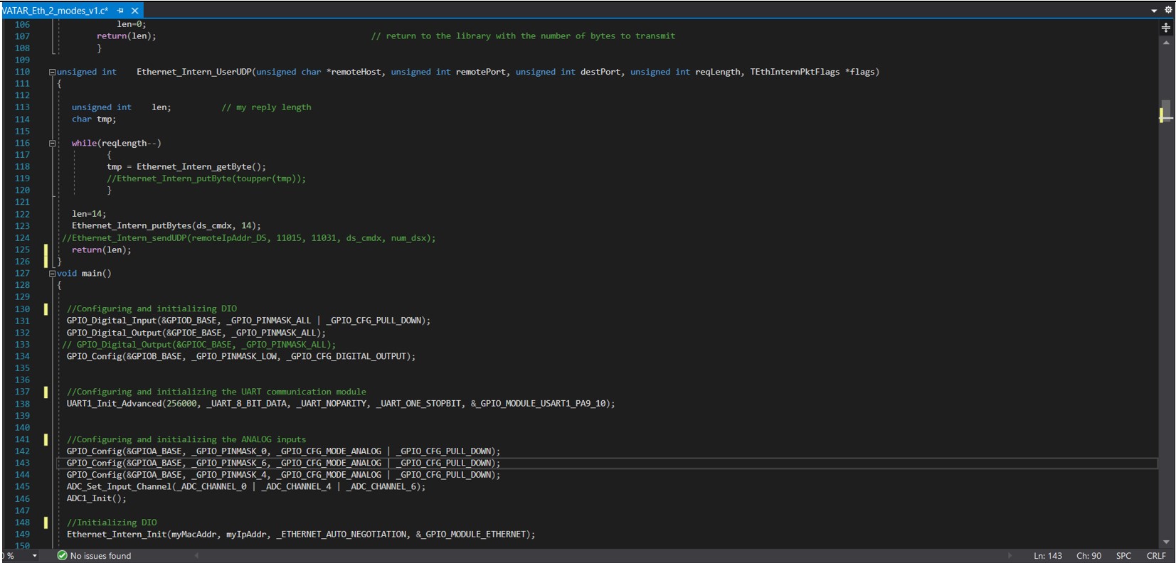
Programing of a MCU
First part of code is module initialization for DIO, UART, ETHERNET and ADC modules. This part of code is shown on the picture. Of course, previously we defined every variable we later used in a code. In the working part of the code, AD conversion, processing of results, formation of a string/message, and sending to the robot control unit are constantly performed in a while loop. Also, there are parts of the program code that set the mode of operation by the Cell Controller via UART. In the most part of the code we are directly calling the MotoPlus routines. MCU is also communicating with the SW API in the PC. There we have a C# program that reads .txt ASCII file. All we had to do here is to convert information about TCP position in to a .txt file so SW API can read it, and we have an operating digital twin!
Cell controller and its main Matlab code
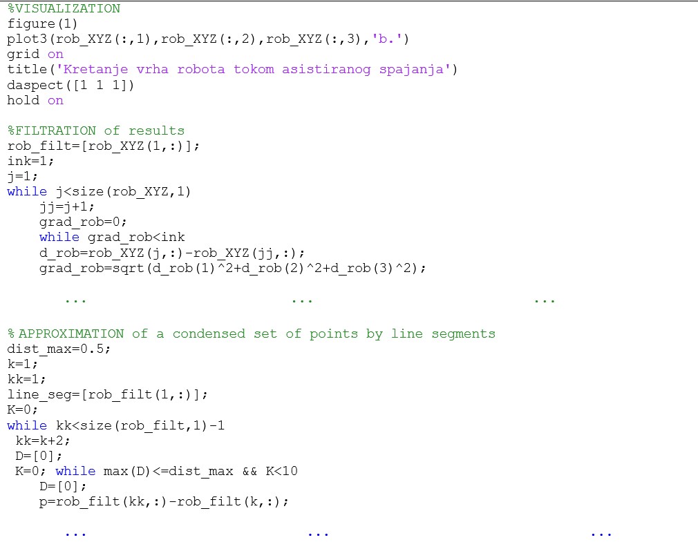
Here we programmed the cell controller in Matlab. Section of the code shown here represents cell controller acquisition of a data flow of a robot trajectory from the MCU. After the acquisition, it does packing and storing of that information. We can reuse recorded values of the robot joint angles any time in the future. In example it can be resend to the robot and move robot’s TCP by same trajectory user moved it with haptic device, or even in reverse. Of course, Matlab is not sending a raw result, first it filtrates results then it sends them back.
Following part of a code is continued part of a previous code. Here, first we’re doing visualizing a raw data robot’s trajectory that came from controller FS100. Next we are doing filtration of received data. Controller is sending joint coordinates with a small error, so we don’t get a straight line when we translate TCP of a robot. That is why we need part of a code that does approximation of a set of points by line segments. After the approximation, we are doing another visualization by plotting that filtrated and approximated results on the same figure with a raw result. On the picture on the right is shown example of the Matlab figure that plotted real movement of the robot after filtration and approximation.
Results
The results of our work were making a functional Digital Shadow, that is shown in the following picture. 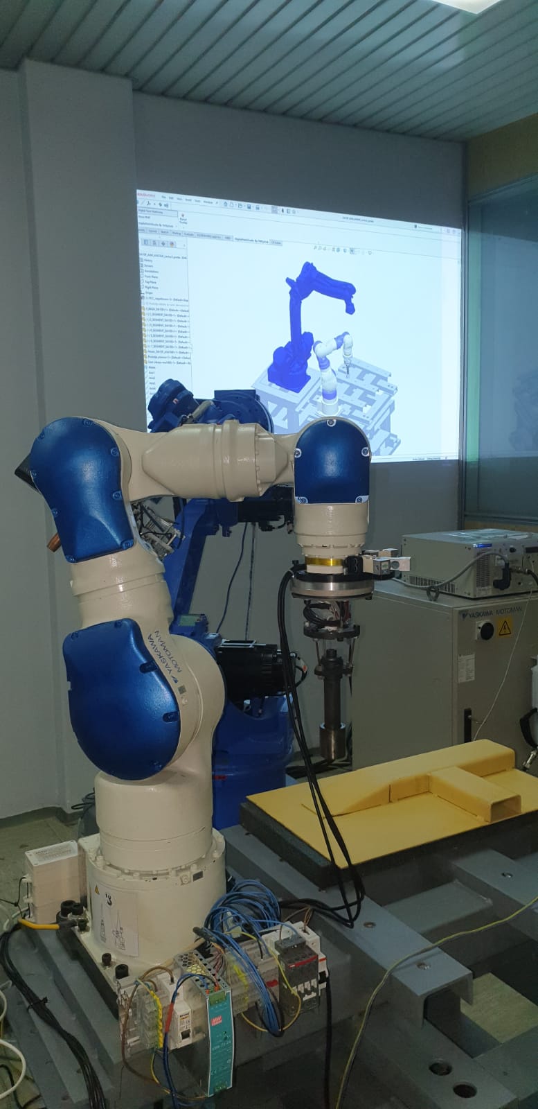
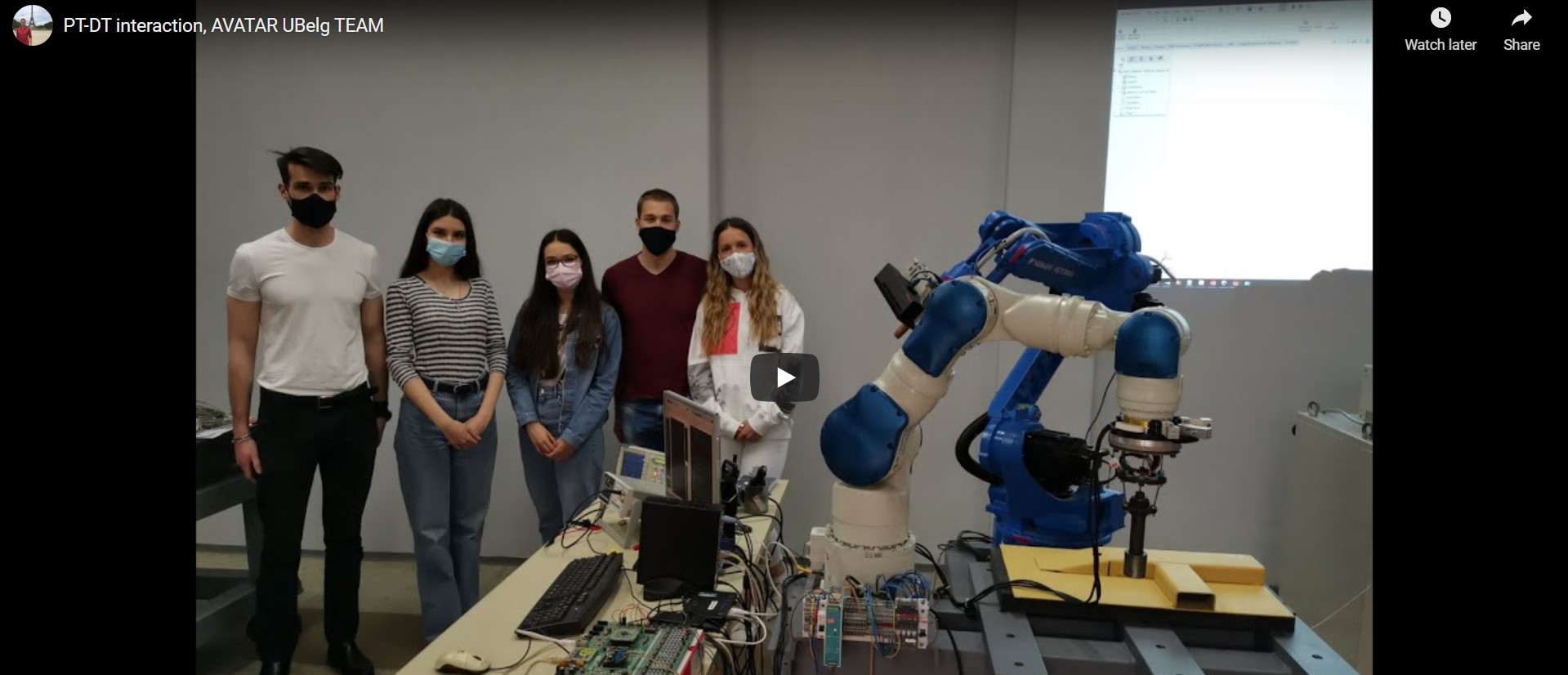
All of this can be displayed in a video that follows.
Conclusion
What we hope to leave for future students is: -We hope to give them a general idea of what a Digital Twin means and what are the needed inputs for a desired output-DT
- That the DT concept can be used in many applications
- Possible solution in specific use cases, so that they can have an example
- Motivation to explore the world of XR technologies for more than just gaming
Avatar for me
Avatar for us meant a lot. We got to work with the amazing team back home, as well as abroad. We learned a lot, and not only technical stuff, but also how to better present our work, how to work in an international team. It was a great experience, from the beginning to end. We are really grateful to have gotten a chance to be a part of this project, and to learn about such an interesting topic as XR technologies. We hope that the future students have the same if not better experience, and we will be here for them if they need us.