Joint Learning Lab 2023 - JLL 2023
The Third Joint Learning Lab - JLL 2022, was held in Milan, Italy and it was hosted by Department of Mechanical Engineering (Politecnico di Milano) and CNR-STIIMA. The event took place from Monday, May 8 to Friday, May 12, 2023.
JLL 2022 brought together 22 students from three partner universities (4 from Grenoble INP, 10 from Politecnico di Milano, and 8 from University of Belgrade) and three countries (France, Italy, and Serbia) accompained with 11 professors and instructors (2 from France, 7 from Italy and 2 from Serbia). Students were divided into 4 mixed project teams to address challenges, with an even distribution by country in order to maximize the international character of the interactions (following the model explained in the Student teams section of chapter organisation). The composition of students project teams was as follows:
Student Project Team A
| No. | Name | Country |
|---|---|---|
| 1 | Karima Sihem Si Youcef | France |
| 2 | Andrea Casiraghi | Italy |
| 3 | Sasha Scarola | Italy |
| 4 | Tamara Kandić | Serbia |
| 5 | Marija Milićević | Serbia |
Student Project Team B
| No. | Name | Country |
|---|---|---|
| 1 | Gweltaz Scordia | France |
| 2 | Giovanni Maggiolo | Italy |
| 3 | Giovanni Spaltini | Italy |
| 4 | Tijana Lukić | Serbia |
| 5 | Pavle Mitrović | Serbia |
Student Project Team C
| No. | Name | Country |
|---|---|---|
| 1 | Kan Ange David Kouakou | France |
| 2 | Enver Eren | Italy |
| 3 | Alessandra Lupo | Italy |
| 4 | Marco Varisco | Italy |
| 5 | Kristina Golo | Serbia |
| 6 | Matija Žuža | Serbia |
Student Project Team D
| No. | Name | Country |
|---|---|---|
| 1 | Kaveh Bekhrad | France |
| 2 | Leonardo Lomacci | Italy |
| 3 | Saverio Rocchi | Italy |
| 4 | Matteo Speranza | Italy |
| 5 | Aleksandar Ćosić | Serbia |
| 6 | Nađa Belić | Serbia |
Welcoming and hosting
The welcome session of the JLL 2023 took place at Politecnico di Milano, Bovisa campus, in room Sala Ovale. Professor Marcello Urgo also addressed the audience with a short presentation of the AVATAR project and planned activities. After the introduction, teachers and students had the possibility to visit the MADE Competence Center at Politecnico di Milano. In particular, the visit focused on the VR Lab and its Cave infrastructure to get familiar with VR/AR technologies. The afternoon session was dedicated to an introductory lecture for the JLL challenges.
Overall organisation of the joint learning lab
The JLL 2023 was structured around two main activities: 1) the VR&Robotics Challenges and 2) the XR Lab Experience.
The VR&Robotics Challenges consisted of:
- Introductory lecture on Monday afternoon
- Visit to the VR and Robotics labs at CNR-STIIMA on Tuesday morning
- Groupwork on the challenges on Tuesday afternoon, Wednesday
XR Lab Experience took place on Thursday and consisted of:
- Visit to the XR Lab at Politecnico di Milano
- Execution of demos and exercises using also XR hardware, e.g. head-mounted display.
The finalization of both activities took place on Friday with:
- Groupwork on final presentation
- Interview of the students to collect feedback
- Presentation of the work carried out during the JLL
Work organization
| Monday | Tuesday | Wednesday | Thursday | Friday | |
|---|---|---|---|---|---|
| Morning | Welcome session | VR and Robotics labs | Challenges | XR lab | Groupwork |
| Afternoon | Lecture | Challenges | Challenges | XR lab | Final Demostration and Project presentation |
Introductory lecture
The lecture on monday afternoon about digital twin and VR/AR technologies in the scope of the AVATAR general workflow. The attention was focused on activities Scene creation (A1), Simulation (A2), and Operation integration (A5).
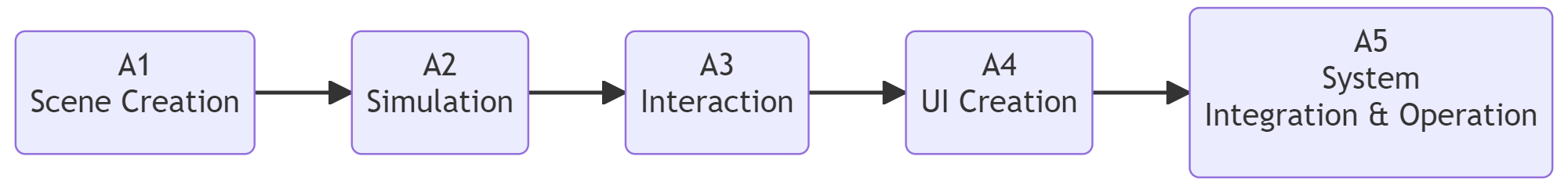 AVATAR general workflow
The proposed workflow and technologies can be employed for any lab and production system, as documented for other use cases.
VR and Robotics lab at CNR-STIIMA
Before starting working with the challenges, students visited the VR labs at STIIMA-CNR and the Robotic lab.
The VR Lab hosts several state-of-the-art devices to develop and demonstrate VR immersive applications, ranging from the industrial to the healthcare domain.
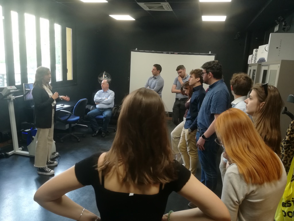
Visit at the VR Lab
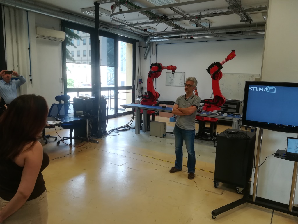
Visit at the Robotics Lab
The robotics lab includes several areas, including the PERFORM Lab (Personal Robotics for Manufacturing Laboratory) that is devoted to the development and validation of methods for the control of industrial and collaborative robots in advanced manufacturing. This lab is structured as an open space populated by heavy industrial robots, collaborative robots and mobile manipulators, in order to create an ecosystem of interacting autonomous machines.
The lab focuses on thematic areas such as human-robot collaboration, task and motion planning, physical human-robot interaction, rapid sorting, human-robot and robot-robot co-manipulation. These topics have applications in various areas in manufacturing, including waste sorting, assembly and disassembly, and pick and pack.
A digital twin of the lab has been developed to support research and teaching activities. Specifically, the generic Scene Creation workflow has been instantiated for the PERFORM Lab, focusing on the activities Geometry modelling (A1 Parts, A2 subassemblies) and Geometric model Scene Creation (A4).
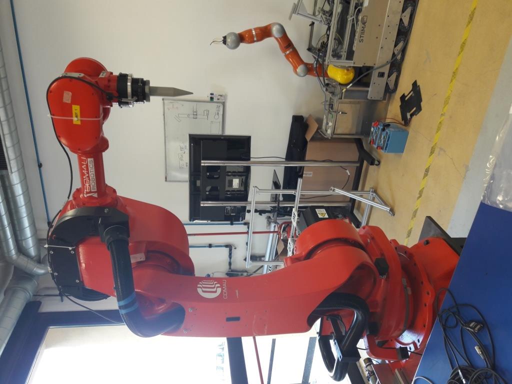
PERFORM Lab
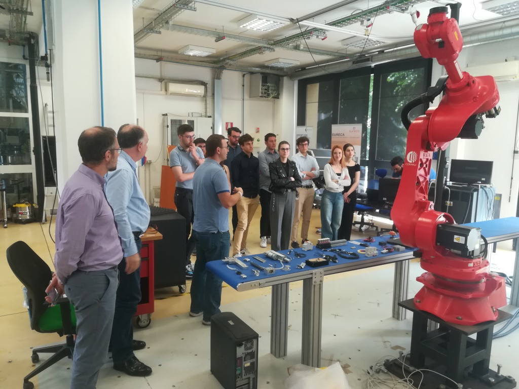
Visit at the PERFORM Lab
Workflow
The main steps of the worksflow are described while providing related data.
1. Definition of assets
The PERFORM Lab consists of several assets placed in the room. Assets are basic elements composing a system, e.g. physical objects like machine tools, parts, conveyors, buffers, but also processes and plans. Herein, only a subset of relevant assets is considered:
- COMAU robots, model NS16 (n.2, Robot_1 and Robot_2)
- bases where the robots are placed (n.2)
- workpieces
- conveyor
- force sensor
- tool (end effector)
- robot controller
- desk
1.1. COMAU robot NS16
The characteristics of the robot are defined in the corresponding URDF (Unified Robotics Description Format) package that is typically used to model robots in ROS (Robot Operating System) applications. In particular, the XML URDF file defines the relevant geometric and functional properties of the robot, including the position and rotation of joints and links, the feasible rotation of each joint, etc.
The URDF package of COMAU NS16 includes 3D meshes and the XML URDF file (cf. comau_ns16hand.urdf). Each joint can rotate only around Z-axis.
The hierarchy of Robot_1 consists of the following elements, where the prefix “Robot_1.” is added to the joint/link name defined in the URDF file to have a unique identifier:
Robot_1 (root)
└ Robot_1.base_link
  └ Robot_1.Joint_1
    └ Robot_1.Link_1
      └ Robot_1.Joint_2
        └ Robot_1.Link_2
          └ Robot_1.Joint_3
            └ Robot_1.Link_3
              └ Robot_1.Joint_4
                └ Robot_1.Link_4
                  └ Robot_1.Joint_5
                    └ Robot_1.Link_5
                      └ Robot_1.Joint_6
                        └ Robot_1.Link_6
Finally, the ForceSensor is attached to Link_6 and the Tool is attached to the ForceSensor.
NOTE 1 The URDF package adopts the following conventions to define the position and rotation of joints and links: Z-up (i.e. Z is the vertical axis); Euler angles XYZ extrinsic (corresponding to ZYX intrinsic)
1.2. 3D models of assets
The 3D models of the assets are available on a GitHub repository in gLFT format, specifically the binary version .glb. The 3D models of the laboratory building, controller, and table were already developed in the past during research activities. The robot 3D model includes nodes for joints and links according to the information in the URDF file; in addition, links are associated with meshes. The 3D model of robot base, conveyor, force sensor and tool were developed with the collaboration of Polimi students (drawings are available upon request).
| Asset | 3D model |
|---|---|
| COMAU robot NS16 | Comau_ns16hand.glb |
| Robot base | Base.glb |
| Controller | Controller.glb |
| Conveyor | Conveyor.glb |
| Force Sensor | ForceSensor.glb |
| Lab building | Lab.glb |
| Table | Table.glb |
| Tool (end effector) | Tool.glb |
| Workpiece | Workpiece.glb |
The .glb file of the robot (Comau_ns16hand.glb) explicitly contains the definition of all its elements in the hierarchy.
The measurements of the robot Tool are provided in the following drawing.
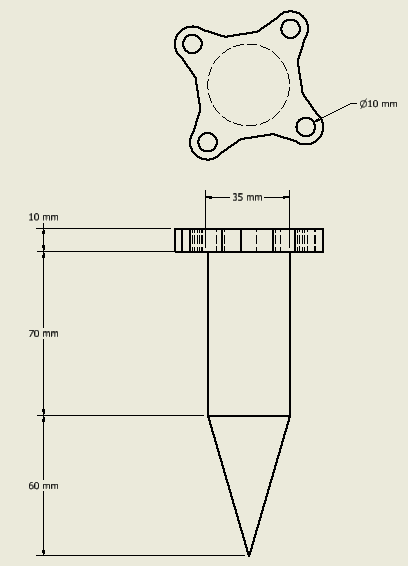
Drawing of the robot tool
If additional 3D models were needed, then several options can be explored:
- Reuse of existing models published in online libraries that can be downloaded (free or with a fee). The 3D models should be available in a neutral format (e.g. .STEP or .IGES) that can be later modified and converted to .gLTF/.glb, e.g. using Blender.
- 3D models can be created from scratch using any 3D CAD (e.g. Inventor, SketchUP, Solidworks) or 3D modeling (e.g. Blender, 3ds Max) software tool.
- 3D scanning of objects and spaces.
More details about the development of 3D models and generation of gLTF files can be found in a specific documentation.
2. Scene configuration
The scene configuration defines the properties of the assets and place them in the layout. Herein, a particular workflow is adopted (see Figure), but other approaches can be followed depending on the available data and target application.
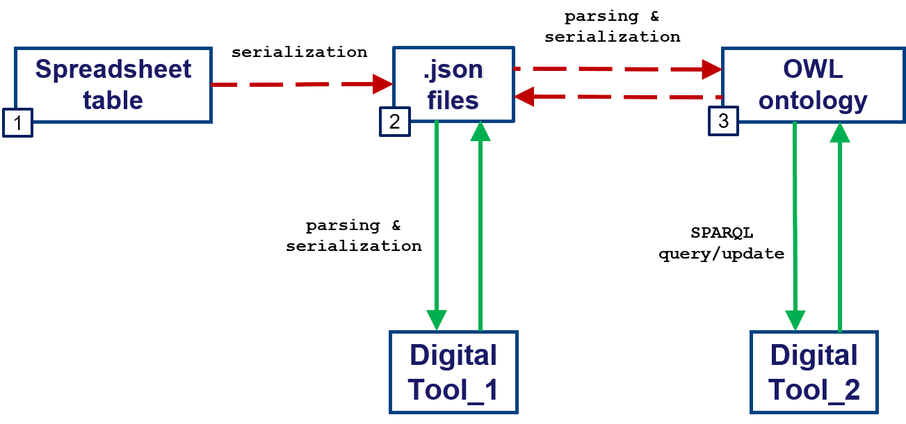
Possible workflow for the scene configuration
NOTE 2 The instantiation workflow reported in this section adopts the following conventions to define the position and rotation of assets in the scene: Y-up (i.e. Y is the vertical axis); Euler angles YXZ intrinsic
2.1. Scene configuration - Spreadsheet table
The scene configuration can be defined in a spreadsheet structured according to a predefined template. The sheet “assets” constains the list of assets with properties (e.g. 3D model, placement). The sheet “context” has cells where it is possible to define the unit of measurment for lengths and the Z-up/Y-up convention; in addition a cell (B1) can be copied to extract the content of the spreadsheet as a JSON file.
The spreadsheet table for the PERFORM Lab is available online. Also in this case the unit of measurement is meter and the Y-up convention is adopeted.
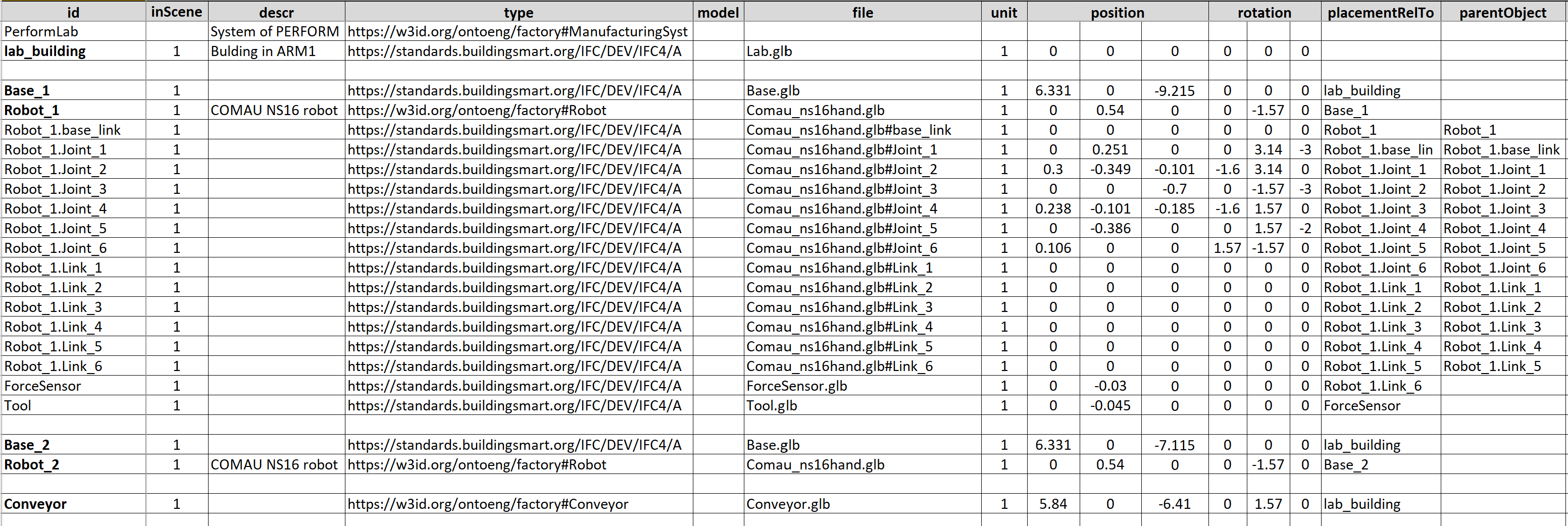
Scene configuration in a spreadsheet table
2.2. Scene configuration - JSON
The scene configuration can be defined in a JSON file according to a specific JSON schema. JSON (JavaScript Object Notation) is a lightweight text-based data-interchange format that is easy to read/parse and write/generate both for humans and machines. A .json file can be opened with any basic or advanced text editor (e.g. NotePad++, Visual Studio Code).
The JSON file for the PERFORM Lab is PERFORM.json. In this case the unit of measurement is meter and the Y-up convention is adopeted.
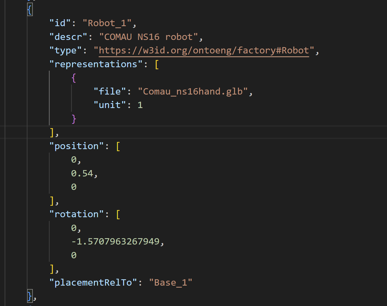
Scene configuration in a JSON file, example of “Robot_1” asset
2.3. Scene configuration - Ontology
Finally, the scene configuration can be defined as an OWL ontology that instantiates the Factory Data Model. The tool OntoGuiWeb can support the instantiation.
3. Visualization in VR environment
The 3D scene can be visualized using several VR tools/environments, such as Unity, UnrealEngine, Godot, BabylonJS, etc.
Herein, VEB.js (Virtual Environment based on Babylon.js) prototype tool is employed, taking advantage of its reconfigurable model-driven approach.
Any browser can be used to visualize the PERFORM Lab with VEB.js.
The documentation of VEB.js provides details about its functionalities, I/O files. The use of the app can be personalized in terms of scene, animation, environment, and configuration by:
- Loading files from a local repository using specific commands in the toolbar
- Defininig URL parameters that point to online resources on a remote repository
GitHub can be used to freely create remote repositories for binary and text files to launch VEB.js with personal settings.
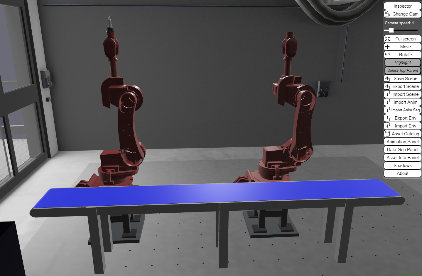
Visualization of PERFORM Lab in VEB.js
4. Simulation
The planning, management, and monitoring of robots are a complex task that can be supported by specific software tools, e.g. Gazebo, RoboDK, Process Simulate, and ROS-based tools like MoveIt.
The attention is focused on the simulation of robot trajectories. However, the actual generation of these trajectories is out of scope as they are taken as input. Specifically, robot trajectories for the PERFORM Lab were generating using ROS-MoveIt.
4.1. Robot Monitoring
During the execution of the trajectory, the robot controller can communicate the joint state (i.e. position, velocity, force/torque, etc.) that in turn can be stored (e.g. in a text-based file) or published (e.g. via MQTT). Herein, we take in consideration only the joint position, i.e. the rotation angle of the joint. The joint angles are likely to be measured by sensors or encoders that are attached to the robot joints. These sensors can generate data at a high rate, potentially several times per second or even faster, depending on the specific application and the performance requirements.
The joint positions of the robot in the PERFORM Lab are saved at 10 Hz (i.e. one position is stored every 0.1 [s]) in a JSON file that contains a list of position items, where each item defines the angles of the joints in radians [rad]. Here below an example of item is shown:
{
    "J1": 0.0,
    "J2": 0.0,
    "J3": 1.57,
    "J4": 0.0,
    "J5": -1.57,
    "J6": 0.0,
    "J7": 0.0,
    "J8": 0.0,
    "J9": 0.0,
    "J10": 0.0
}
Each item of the list reports by default the value of 10 joint angles. Robot_1 of PERFORM Lab consists of 6 joints, therefore only joints from “J1” to “J6” contain relevant values while the others (from “J7” to “J10”) will be always set to zero.
NOTE 3 Based on the structure of the robot generated after its URDF package, the position (angle) collected during monitoring for each joint must be actually applied to the child of the joint, i.e. a link. For instance the angle of “J3” (referring to Joint_3) must be applied to its child link Link_3.
An example can be seen in file trajectory_example.json that defines a trajectory moving the tool along the vertical axis.
4.2. Robot animation in VR environment
Most of the VR environments enable interactions and animations that can be exploited to visualize the exectution of robot trajectories. However, the messages generated during robot monitoring require an elaboration with the addition of contextual data to support a proper animation. Herein, the animation of assets in a VR scene can be formalized according to a specific JSON schema that enables the definition of several events, such as show, hide, animation, state, etc.
NOTE 4 Also the instantiation of the animation JSON file follows the conventions Y-up and Euler angles YXZ intrinsic. |
According to the content of the URDF file, all robot joints can rotate only around Z-axis in a Z-up convention. This means that the rotation angle collected during monitoring must be converted into a rotation around Y-axis, while preserving the sign of the angle. For instance, a +1.57 [rad] angle for “J3” (i.e. Joint_3) means a rotation around Z-axis that is converted into a rotation [0, +1.57, 0] radians of Link_3 (cf. NOTE 3).
The animation corresponding to the example trajectory is provided in file PERFORM_anim.json.
The animation of the example trajectory can be played in VEB.js pushing the play button in the animation panel.
5. MQTT Communication
MQTT (Message Queuing Telemetry Transport) is a lightweight, publish-subscribe messaging protocol that is commonly used in the Internet of Things (IoT) and other applications.
MQTT can be exploited for bi-directional communications with robots:
- sending feedback about joint states
- receiving commands for the execution of trajectories
Different programming languages can be used to develop MQTT clients, e.g. JavaScript and Pyhton libraries. In addition to publishers and subscribers, the MQTT architecture needs a broker to manage messages.
Several resources are freely available online to develop MQTT architectures:
- tools to develop and test MQTT architecture/components (e.g. MQTTLens)
- free public MQTT broker (e.g. broker.emqx.io)
- desktop MQTT client (e.g. MQTTX)
- tutorials on MQTT and related tools (e.g. this)
- libraries to develop MQTT components (e.g. MQTT.js)
The robot controller can publish a message containing the current joint states. Because of security resons, the messages can be generated by an emulator of the robot controller that is launched using the web application OntoGuiWeb. Specifically, the module MQTT Sync provides functionalities as an MQTT client to publish messages and subscribe to topics.
VEB.js can play the role of both publisher and subscriber, exchanging messages that are structured to the animation json schema.
Challenges
This section presents the challenges making reference to the workflow. The aim of the challanges is to make practice with digital twin and VR technologies addressing a simplified problem that still makes sense from an industrial perspective while using real data.
Scene Configuration
The PERFORM Lab is considered for the setup of the challenges. The scene is configured as described in the main documentation, with the addition of one or more workpieces on the conveyor. Each challenge makes reference to its own scene configuration, thus highlighting the reconfigurability of the digital twin.
VEB.js can be employed to visualize the scene configuration using 1) local files or 2) specifying URL parameters pointing to remote files. In particular, the challenges will ask to personalize the animation. This is a full example showing the setting of all relevant URL parameters, if the second option is chosen:
It is recommended to keep unchanged the value of parameters repoMod3d and inputenv. The value of inputscene will change according to the setup of the challenge. The value of inputanim must be personalized according to the results of the development tasks.
Trajectories
The robot trajectories are meant to reach the goal of the operation (for all challenges), i.e. to place the robot tool (i.e. end effector) inside the hole of Workpiece_1.
Tasks
Specific tasks are defined for each challenge. The output of each taks will be documented in the final questionnaire.
Challenge #1 - Visualize Trajectories
Scene configuration
- spreadsheet
- json file
- VEB.js visualization (without setting of the animation, the string “linkToBeAdded” must be replaced accordingly).
Trajectory
The following trajectories are provided as list of joint positions defined in a JSON file:
Tasks
Task T.1.1
Using a VR tool that you can freely choose, visualize the scene configuration of the PERFORM Lab in a VR environment and zoom-in to identify specific assets by highlighting their local origin:
- Tool of Robot_1
- Conveyor
- Workpiece_1
- Workpiece_6
Bonus: the fast solution is to use VEB.js for the visualization. A bonus will be awarded if also another VR tool is used to visualize the scene.
Output: 1) Screenshots of the VR scene; 2) Configuration files and instructions, only if a VR tool different from VEB.js is used for the visualization.
Task T.1.2
Elaborate the 4 trajectories (joint positions) and generate an animation that can be played in the selected VR environment (e.g. animation for VEB.js).
Output: 1) Animation files of the 4 trajectories for VEB.js or equivalent configuration of a different VR environment to play the animations; 2) Script/program to elaborate the trajectories.
Hints: the input trajectories can be elaborated using any programming language, e.g. Python, C++, Java, JavaScript, etc.
Task T.1.3
Visually check the animation behaviour in the selected VR environment.
Output: Video of the 4 trajectories in the selected VR environment.
Hints: the animations can be loaded from a local file or a remote repository if VEB.js is employed.
Task T.1.4
Assess the execution of the trajectories in terms of distance from the target and possible collisions.
Output: 1) Does the trajectory reach the goal (yes/no)?; 2) Identification of possible collisions of the robot or tool with other assets; 3) Distance of the tip of the Tool from the local origin of Workpiece_1;
Hint_1: The assessment of the trajectory can be carried out using different methods, e.g. a) visual check in VR environment, b) geometric calculations using data exported from the VR environment, c) execution in a robot simulation tool, d) other methods.
Hint_2: VEB.js can be exploited to calculate the relative distance between assets, cf. the functionalities of the Asset Info Panel.
Hint_3: Consider the drawing of the robot tool to calculate the precise distance of the tool tip from the origin of the workpiece.

Origin and bounding box of the robot tool

Origin and bounding box of the workpiece
Challenge #2 - Receive a Trajectory via MQTT
Scene configuration
- spreadsheet
- json file
- VEB.js visualization (without setting of the animation, the string “linkToBeAdded” must be replaced accordingly).
Trajectory
The trajectory for this challenge is not provided in a json file, but it can be received as separate messages via MQTT communication. The trajectory of this challenge can be generated using the MQTT Sync tool of OntoGuiWeb by pushing the button “Start Publish” on the right of the text “Challenge#2 Sequence”, thus emulating the generation of messages that would do the robot controller. It is recommended to personalize the Topic to publish the message sequence, since other people could use this functionality at the same time.
Tasks
Task T.2.1
Launch the emulator of the robot controller to generate the sequence of messages containing the joint positions, thus defining the trajectory. Save the trajectory to a text-based file.
Output: Trajectory of the robot in a text-based format (e.g. similarly to the input trajectories of Challenge#1.
Task T.2.2
Elaborate the trajectory (joint positions) and generate an animation that can be played in the selected VR environment.
Output: Animation file of the trajectory for VEB.js or equivalent configuration of a different VR environment to play the animation.
Task T.2.3
Visually check the animation behaviour in the selected VR environment.
Output: Video of the trajectory in the selected VR environment.
Task T.2.4
Assess the execution of the trajectory in terms of distance from the target and possible collisions.
Output: 1) Does the trajectory reach the goal (yes/no)?; 2) Identification of possible collisions of the robot or tool with other assets; 3) Distance of the tip of the Tool from the local origin of Workpiece_1.
Task T.2.5 (Bonus)
Develop an MQTT client that is able to 1) receive the messages sent by the robot emulator (using OntoGuiWeb), 2) elaborate the content of the message an animation, 3) publish the animation via MQTT, 4) play the animation in the selected VR environment in quasi-real-time.
Output: 1) Program/script implementing the MQTT client; 2) Explain how the MQTT client was developed and how it works.
Challenge #3 - Generate a Trajectory
Scene configuration
- spreadsheet
- json file
- VEB.js visualization (without setting of the animation, the string “linkToBeAdded” must be replaced accordingly).
Trajectory
No previously generated trajectory is provided for this challenge.
Tasks
Task T.3.1
Generate a trajectory for the robot using any support method/tool that you like. The starting position is defined by the following list of joint positions:
{
    "J1": 0,
    "J2": 0,
    "J3": -1.57,
    "J4": 0,
    "J5": 1.57,
    "J6": 0
}
The target position is the same as for the other challenges, i.e. the hole of Workpiece_1.
Output: 1) Description of the workflow to generate the trajectory, including a) choice of the tool/method, b) setup of the scene, c) generation of the trajectory, d) exporting the trajectory to a text-based format; 2) Trajectory of the robot in a text-based format (e.g. similarly to the input trajectories of Challenge#1.
Task T.3.2
Elaborate the trajectory prepared in Task T.3.1. and generate an animation that can be played in the selected VR environment (e.g. animation for VEB.js).
Output: Animation file of the trajectory for VEB.js or equivalent configuration of a different VR environment to play the animations.
Task T.3.3
Visually check the animation behaviour in the selected VR environment.
Output: Video of the trajectory in the selected VR environment.
Task T.3.4
Assess the execution of the trajectories in terms of distance from the target and possible collisions.
Output: 1) Does the trajectory reach the goal (yes/no)?; 2) Identification of possible collisions of the robot or tool with other assets; 3) Distance of the tip of the Tool from the local origin of Workpiece_1.
XR Lab
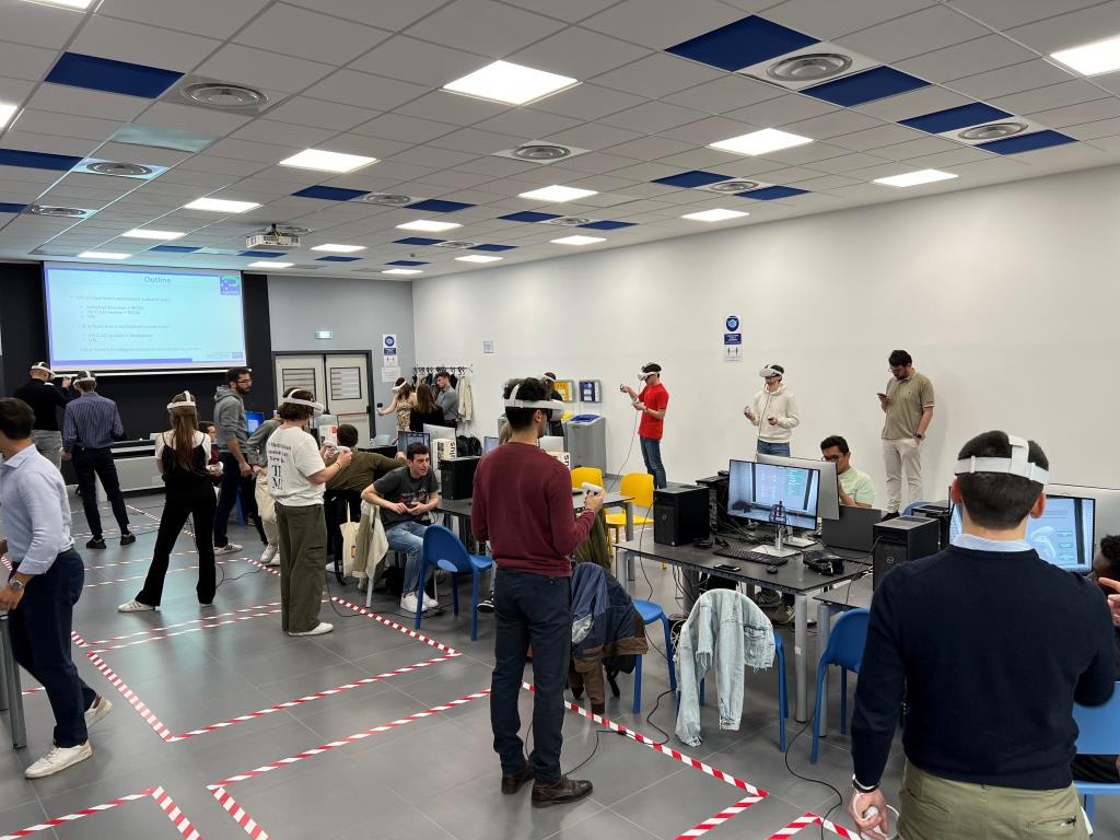
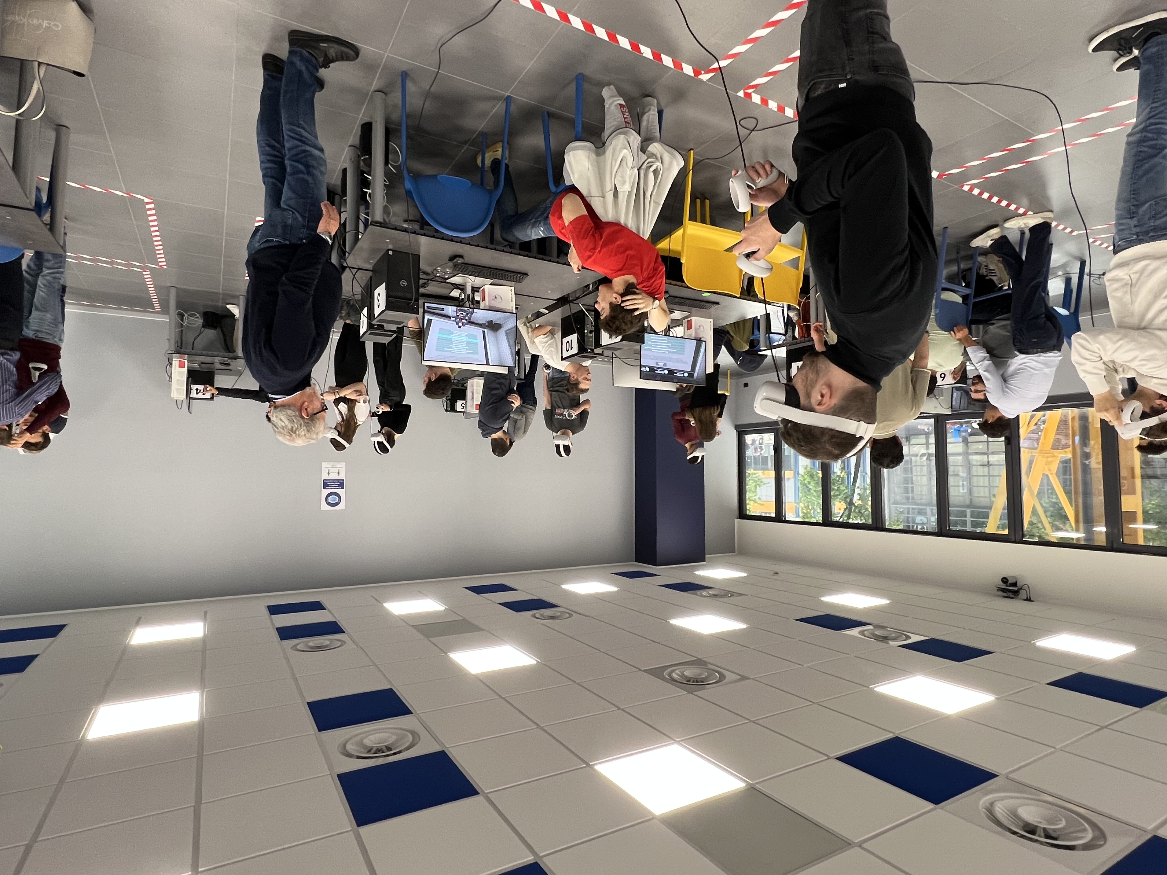
On Thursday, the students had the possibility to directly work with Head-Mounted Displays (HMDs) and the Unity software. The lab has been held in a dedicated room (L04, Bovisa Campus) equipped with 15 HMDs (Meta Quest 2) and PC with all the development kit installed. The main topic of the day is related to the use of Virtual Reality (VR) for engineering education. After getting in contact with some possible applications dealing with a robot and a gearbox, they worked to track their movements with a special camera and animate a 3D model in Unity environment. More specifically, the whole day has been organized in three learning experiences:
- How to use VR to learn how a mechanical system is made,
- How to use VR to learn how a mechanical system works,
- VR to learn how integrate humans in manufacturing systems.
The first two experiences where thought to get the students used with VR immersive environments and HMDs scene navigation and interaction mode and get them aware of the potentiality of VR for education. During the third activity, they were asked to implement the integration of humuna movement in a VR application of a collaborative workstation by using simple motion capture system.
After a brief introduction on how the whole setup works, the students were asked to wear the HMDs and start with the first learning experience. As the scope of the first experience is to use VR to learn how a mechanical system is made, the proposed application allows student to explore and interact with a mechanical gearbox. The main idea behind this application is to use VR to mimick what would be the experience of using a real mechanical system. This will get the student closer to a real “hands-on” learning activity without the need of having the real mechanical assembly, making it safer and engaging even in a university classroom.
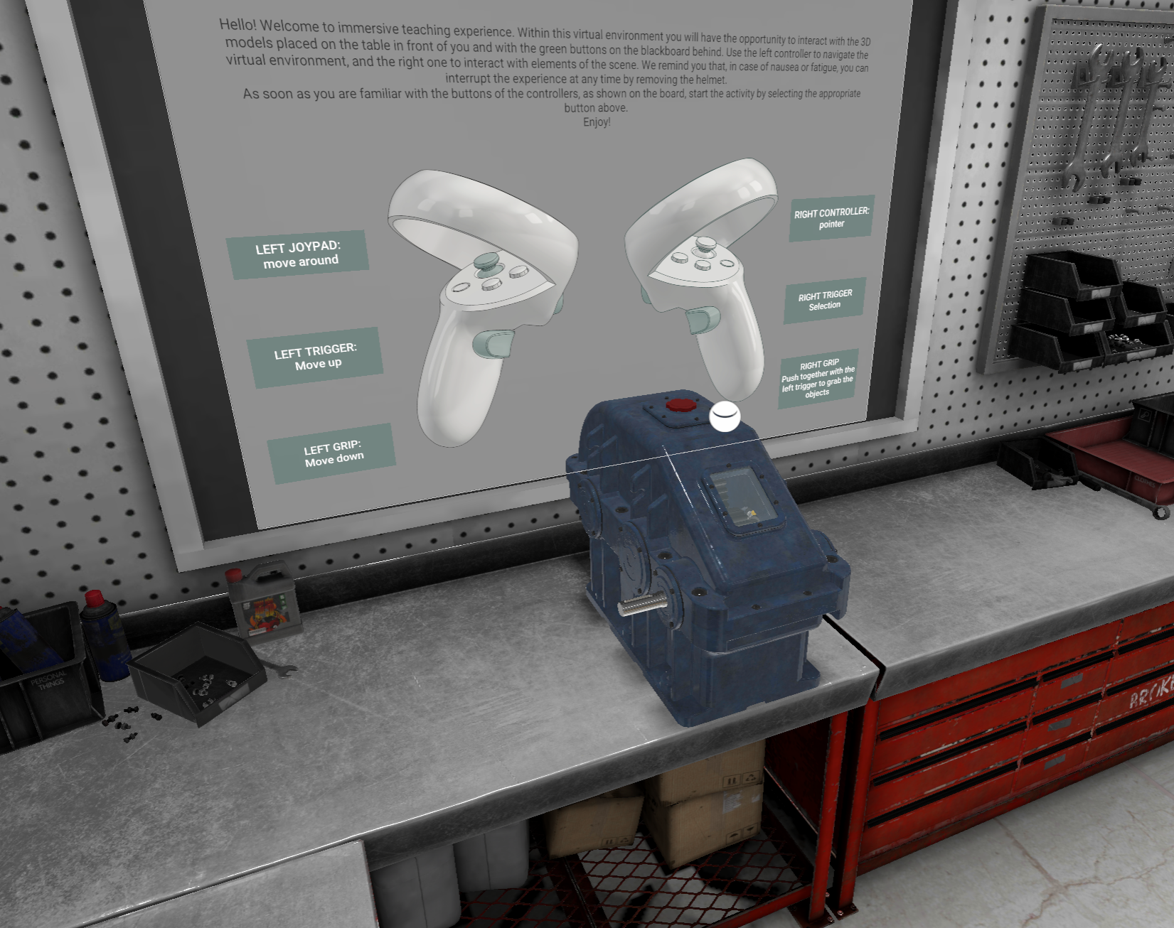
The gearbox part is grabbable and selectable and the student can disassemble the different elements of the gearbox with and without precendence constraints. The exercise aims at mimicking the real process of disassembly of the gearbox. While disassembling, the students can select the parts and check their name and technical representation on the blackboard behind the desk. The students can also explore the Bill of Material (BOM) related to the gearbox and the assembly drawing.
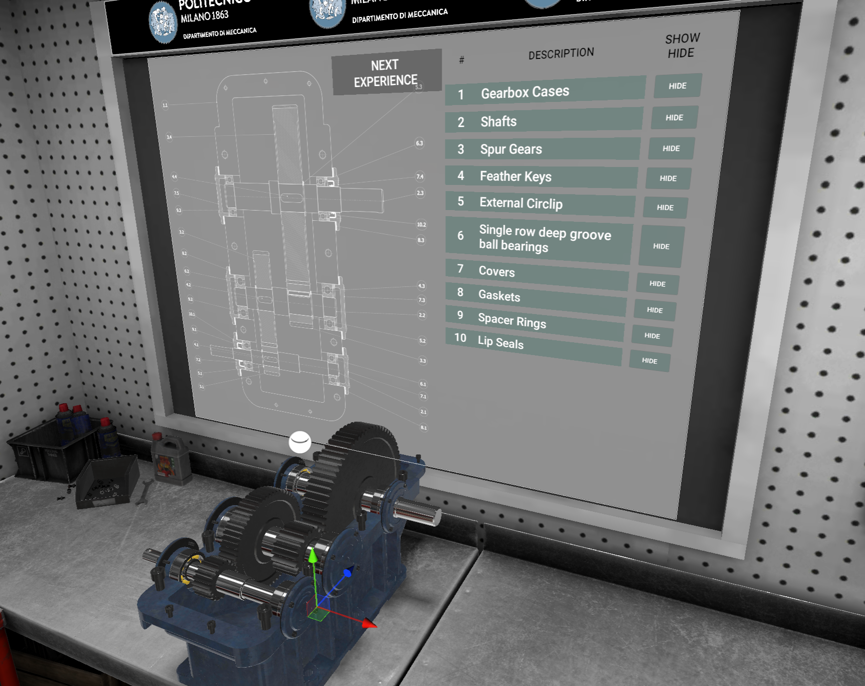
Moreover, the application also give the students to explore the mechanical system in terms of exploded views, with specific close-up on the main machine elements details (e.g. bearings, fasteners, etc). Beside the immersive exploration of the 3D environment, the application also includes some small tests with real-time feedbacks to help students checking their knowledge and understanting during the experience.
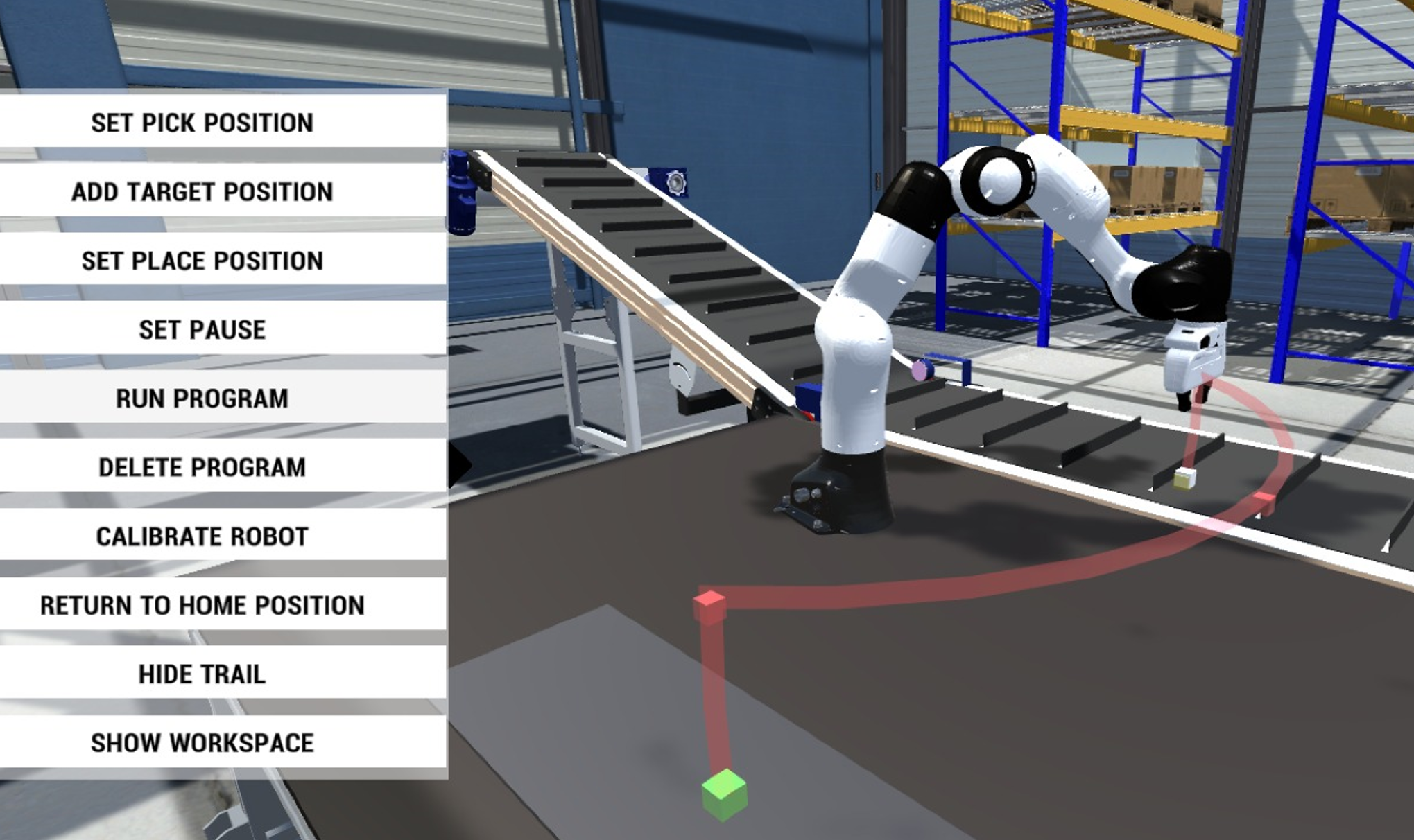
The second experience addresses the problem of learning how a mechanical system works. The main idea behind this second experience is to improve the knowledge and understanding of the behavior of complex mechanical systems (e.g. a robot) through a direct correlation between the theory and its realization (e.g. the algebra governing the robot and how the robot actually move in the space). The application focuses on a robotic application, specifically the virtual representation of a Panda Emika collaborative robot is exploited. The experience was oriented to understand the architecture of a robot, forward and inverse kinematic problems as well as path planning issues of a simple pick and place task. Specifically, the students were asked to build up the kinematic chain of the robot by dragging the components in the correct order. Once done, the reference frames according to the Denavit–Hartenberg convention appear in the VR environment along their matrix representation. The student can now play around with the values for the joint parameters and look what happens at the end-effector (forward kinematic). Finally, the inverse kinematc problem and path planning issue is introduced through a simple pick and place task. By moving in the space the position of two cubes, representing the pick and the place position of the task respectively, the students can observe how the cobot behave in a situation where the end-effector pose is specified and the variable joint parameters should be computed.
As the first two experiences were used to give student insight and clues on how VR can actually work for education purposes, the third activity of the XR Lab has been designed as an hands-on experience where students can get theor hand dirty by using acquisition system and a VR editor. During the third activity of XR lab day, the students learnt about motion capture using state-of-the-art, off-the-shelves sensor solutions. The goal of the lesson was to learn how to animate 3D Virtual Human Avatars so that their motion could effectively and realistically represent a collaborative human-robot scenario. Such a Virtual Human can be included in a virtual application, for example with training purposes, where the learner can experience the correct way to interact with a cobot.
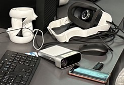
As a test case, a single basic activity that must be performed by human hands was selected for being virtually replicated. In the chosen test scenario, a single metal object has to be rotated of 180° along its major axis as part of its manufacturing process, before being collected by a robot arm. Since this rotation is a task extremely complicated for a cobot to perform, human intervention is mandatory. The capture of motion from a human “actor” is a non-trivial task that involves expensive hardware both specific skills from those operating it. To lessen the technical requirements for the students, sensors like the Azure Kinnect and the Leap Motion were adopted for recording the actions. The first one can accurately map the general (gross) motion of the human body, that doesn’t include all of the fingers movement, while the second is hands motion specific (fine). The idea was to combine the animations recorded from the two sensors in one, representing the full manufact manual rotation and apply it to a virtual character.
The students, split into groups, were instructed, in the first part of the seminary, about the use of the two sensors. In particular, they learnt how to include in a Unity project the libraries required to operate the sensors and record the animation in Unity native anim format. Since the final scene of human-robot interaction was to be assembled into a Unity project also, this pipeline was intended to minimize import-export and compatibility issues with the animation files. In the second part of the seminary, the students had the opportunity to challenge themselves with the recordings of gross and fine motion. Some in the groups were designated as recorders, others as the actors replicating the manufact rotation movements. The acquisition of actors’ motion required several trials to obtain the needed verisimilitude level.
The two final animations selected by the groups where then mixed using the animation mask feature of Unity and applied to a virtual avatar. Using the mask, only selected joints of the bones system animating the character are affected by the recordings. In this way, the mixing of fine and gross motion was of straightforward application.
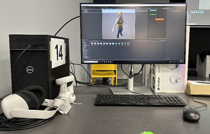
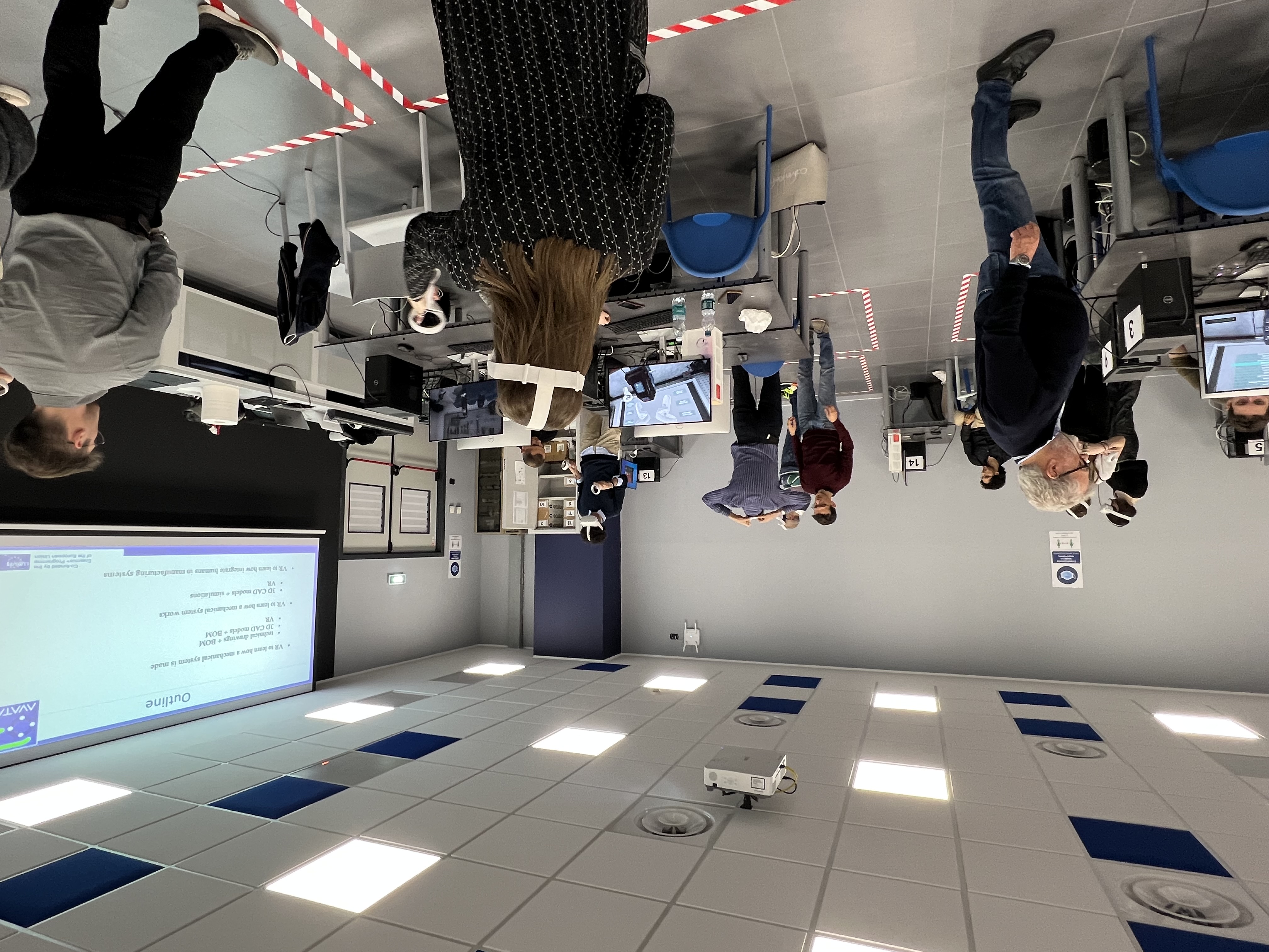
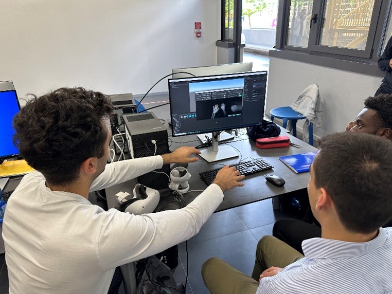
Student activities in the XR Lab
Groupwork activities and final presentation
Groupwork activities were aimed at solving the proposed challenges and tasks during the JLL week.
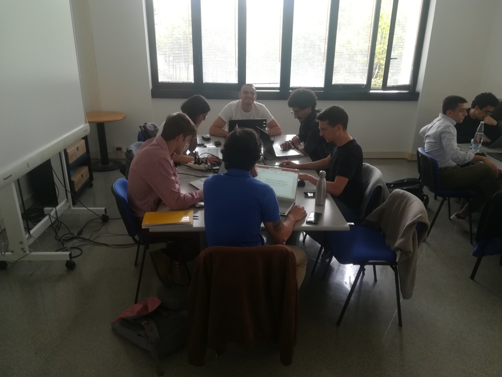
Groupwork activities at CNR-STIIMA (1)
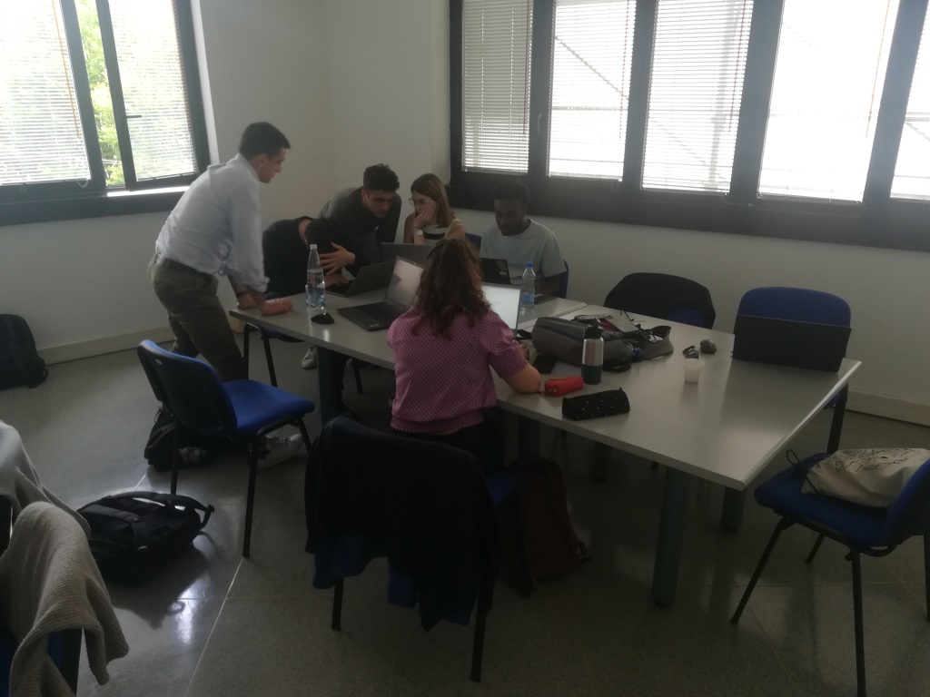
Groupwork activities at CNR-STIIMA (2)
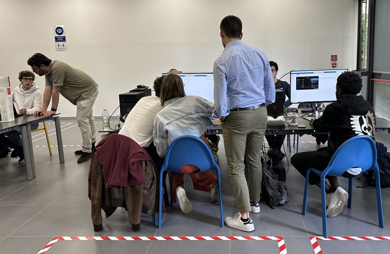
Groupwork activities at POLIMI (1)
The last day was dedicated to the preparation of the final presentation that took place in the afternoon. Each group made a significant effort and successfully achieved the goals set for the JLL week.
![]()
Final presentations at POLIMI (1)
![]()
Final presentations at POLIMI (2)
Result of Challenge #1 using VEB.js
Result of Challenge #2 using VEB.js
Result of Challenge #3 using Unity3D
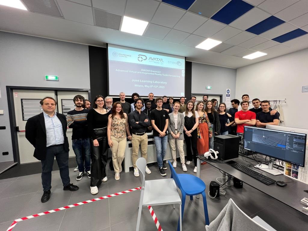
Group photo with tutors and students
![]()
Closure of the meeting and farewell