JLL 2022 - Team 3
Overall team objectives
CAD-based XR SCENE CREATION
- XR SCENE ANIMATION – RWC Kinematics Modeling
- XR SCENE ANIMATION – HMD Installation and interactions
- Step I –RWC DIGITAL SHADOW
Integration
- Step II –RWC DIGITAL TWIN Integration
- RWC DIGITAL TWIN Robot PbD using Digital Shadow I
- RWC DIGITAL TWIN Robot PbD using Digital Shadow II
- RWC DIGITAL TWIN XR Robot PbD using full Digital Twin
JLL DAY 1
On the first day of the JLL, the professors started with a brief presentation of the University of Belgrade and their relative courses. They then went over the weeks Joint Learning Lab’s schedule and topics. We discovered the main features of the project and all the advantages it would bring us in terms of specific VR and Robotics knowledge.
In the afternoon we started with the first “workshop”, session in which we covered the review of basic CAD modelling skills. The key concept was to know which modifications had to be implemented on the existing CAD models. This was done in order to be able to open it in a virtual scene.
Firstly, we had to check if the measurements of the CAD model were coherent with the ones of the physical robot. Secondly, we had to apply for each link, a coordinate system. This had to be done in order to make sure that future implementation in unity would not have errors.
The model we worked on was the MOTOMAN SIA 10F, and we were able to download the entire rigid body from the YAKASAWA website.
The next step was to export the model in a .gltf format. To do so we had to firstly open the model in Solidworks’s Visualize Professional, after adding the Visualize Professional Add-In in the Solidworks app. We then exported the project into the .gltf format.
Now we had to prepare Unity: by going to Package Manager and adding a package via Git URL, we added the UNIGLTF package. The robot was ready to be imported into Unity: after allocating the .gltf file into the assets folder of the project, with a simple drag and drop in the scene, we had the robot ready to work with.
JLL Day 2
Morning session:
What we have done:
- Coordinate system changing
- Direct and inverse kinematics explanation
- Programming of the physical robot
Once we imported our system into Unity, we noticed that our coordinate system wasn’t working properly. The coordinate base orientation was different in Unity and in our CAD model. This is because our robotic arm’s links rotate relatively to the parent’s coordinate system. To make sure this problem wouldn’t drag on we had to change them. We added a new coordinate system identical to the one in Unity on every joint by assigning a point on every link.
After this, we saw the differences between the direct and inverse kinematics and their applications.
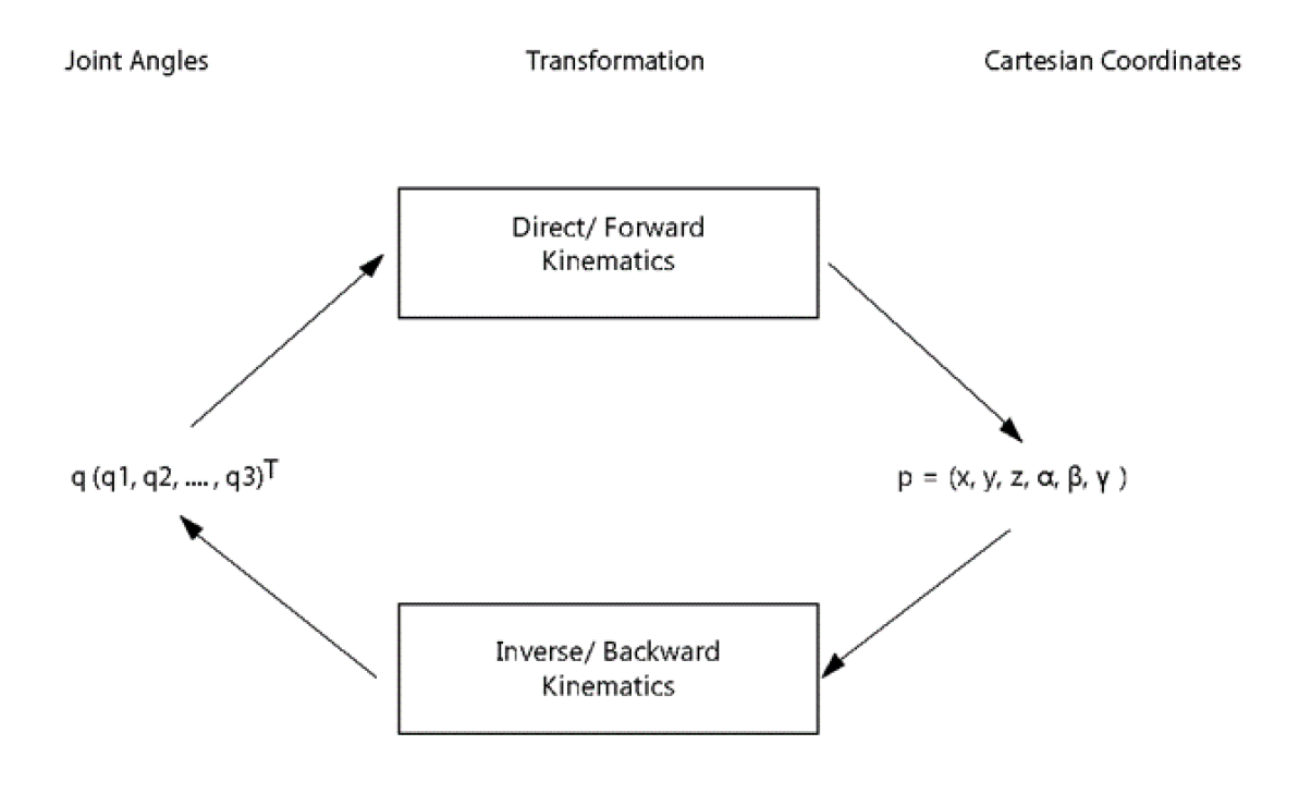
Direct kinematics refers to the use of the kinematic equations of a robot to compute the position of the end effector from specified values for the joint parameters. Inverse kinematics refers the reverse process that computes the joint parameters that achieve a specified position of the end effector.
Knowing this, we proceeded in visualizing the robot in RoboDK. This software is able to implement the inverse kinematics, thus enabling us to plan and execute trajectories. During the movements we could see the various angle changes. Being a 7 degree of freedom robot, we had the possibility to choose different configurations, since the 7th degree is redundant, giving us multiple solutions.
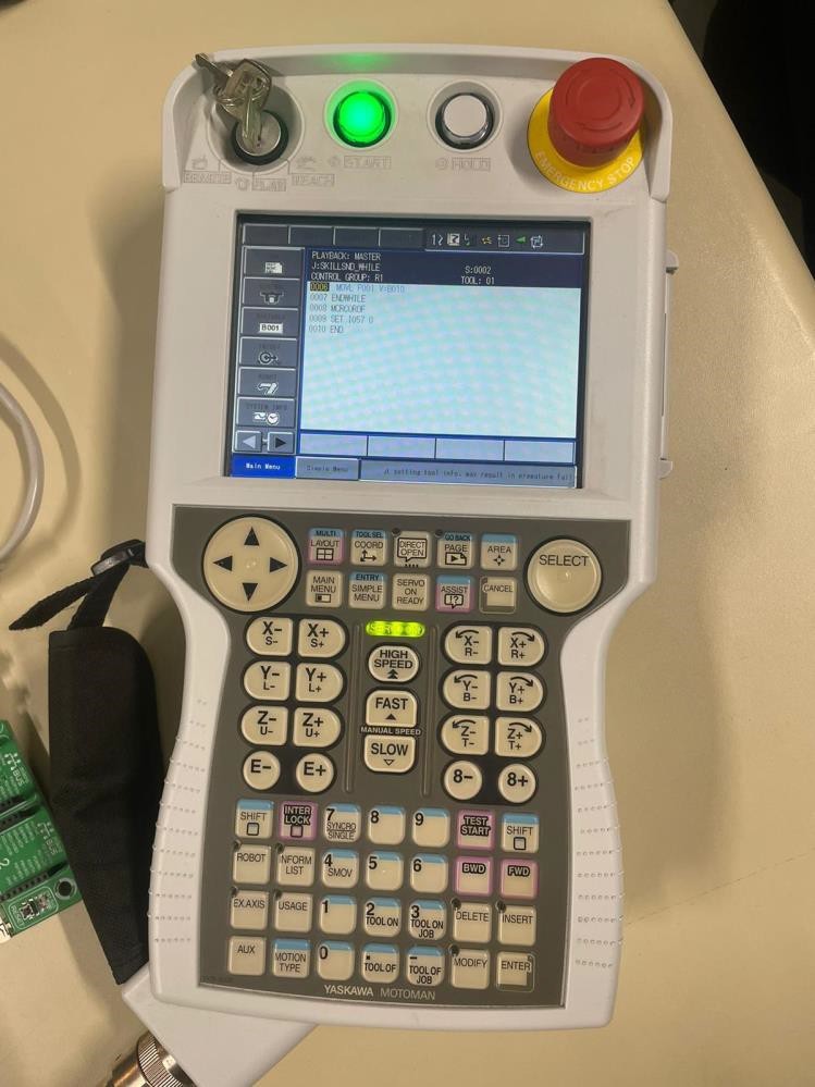
We then went to physically see the robot and manually teach it the points where to move. To teach it the positions in which to move we have to be in teach mode with server on. We then move the robot whilst pressing down on the dead man’s button. Once in the desired position we have to save its coordinates by clicking on the insert button and then the enter button. Before playing the movement, we should check it by scrolling through the saved positions.
After setting those points, we can start our program. It will go from saved point to save point with the type of movement we set for each of them. (We have to switch to play mode and be sure that the server is on).
JLL DAY 2
Afternoon session:
OBJECTIVES:
- Robot kinematics, robot joint and robot arm linkage / mechanism;
- Robot motion demonstration using TEACH PENDANT (online programming method), single joint motion, robot arm motion;
- Adding kinematic features to the XR robot models and demonstration of robot joints motion in virtual space;
- Inverse kinematic transform using RoboDK simulation software, JOB TASK creation and TARGET POINT concept;
- Integration of RoboDK in UNITY and demonstration of robot arm motion;
- Linking CAD model with XR UNITY model using SW API SDK and UNITY scripts written in C#
After lunch break, we had a lesson on the connection between Unity and SolidWorks:
The link between SolidWorks and Unity was established using an API which is open source. The connection used was UDP. A while loop is running. inside the while loop an If conditioned is used to check if there is any data transmitted (angle for the joints etc..), if there is no data waiting in the queue the program runs the else condition, if the software has a change in angles superior to 0.01 the UDP protocol for sending starts.
User datagram protocol (UDP) operates on top of the Internet Protocol (IP) to transmit datagrams over a network. UDP does not require the source and destination to establish a three-way handshake before transmission takes place. Additionally, there is no need for an end-to-end connection.
Since UDP avoids the overhead associated with connections, error checks and the retransmission of missing data, it’s suitable for real-time or high performance applications that don’t require data verification or correction. If verification is needed, it can be performed at the application layer.
We also discussed the connection between Unity and RoboDK. In Unity we can move the robot’s TCP (tool center point). For every frame, the TCP’s position and rotation is sent to RoboDk by using APIs. Once the TCP’s orientation and position are obtained, RoboDK calculates the inverse kinematics, which implicitly means its joints angles. After this we use APIs once more to send back to Unity the robot configuration. Depending on the frame rate, the robot position refreshes to the exact configuration.
So, once we had the scene, we started to visualize it in VR environment. Virtual reality immersed us in a digital environment, with which we could also interact thanks to the use of special joysticks. The oculus used is composed of one screen that transmits two images that are slightly shifted. Thanks to the different orientation of the lenses the two images overlap giving the sensation of depth. The device needs a camera to work and it has connection points in order to control the tracking. Thanks to this technology we could see the representation of the robot, interact with it and see its parts.
    while(true)
    if (udp client.canRecieve() > 0)
    {angles = parserUDP.udpRead();
    Set angles (angles);
    Array.Copy(angles, 0, old angles, 0, angles.Length);
    else
    {
        angles = Get angles();
        {
            if (!Array Sequence_Offset (angles, old_ angles, 0.01))
            {
                Array.Copy(angles, 0, old_ angles, 0, angles.Length);
                udp_client.udpSend(angles);
            }
        }
        XR CAD();
    }
This part of the code represents the algorithm used for communication between SolidWorks and Unity. The while loop is executing until we close the program.
First, we are asking the UDP client if he received some information from unity, if this is true, we are reading the information that is sent to us and we ask SolidWorks to update angles, after changing we store them in the variable old_angles so we can compare those angles with new ones when we need to.
If we didn’t change the angles in Unity, we are entering the else part and there we
check if the difference between new angles and angles in SolidWorks is more than
0.01. If this is true the new angles are becoming old angles and we sent that information to unity using UDP.
JLL DAY 3
Morning session:
Objectives:
- Create a communication between the robot control unit and Unity using UDP, implemented in UNITY scripts written in C#
- Open architecture control unit explanation and digital shadow creation
On this day we brought an interactive connection between the physical world and the abstract one. At the end of the session, we were able to read joints coordinate in real time thanks to OAC (Open Architecture Control).
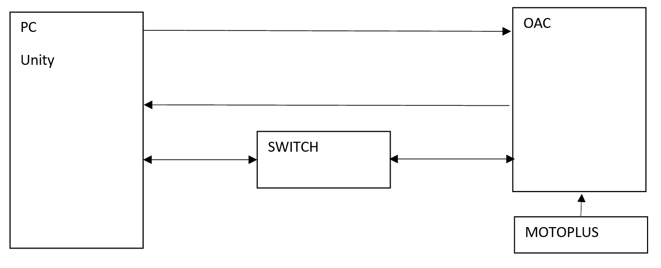
In a digital shadow, you have a one-way communication between your digital robot and the real one. This basically means that the digital robot copies the movement of the real one. We were then taught what functional blocks were needed for a digital shadow. The physical robot in this type of configuration is a “Publisher” which publishes the states (the angles positions) of every joint of the robot. Our digital interface, or Unity, is our “Subscriber” which receives all the data sent by the publisher. To make these two talk we have to establish a UDP type of connection. To make this “topic” travel we use APIs and the connection is physical between the two parts through an ethernet connection thanks to the switch.
We use Robot Open Architecture Controller to gather all the information we need to create the digital shadow: the angles of the joints. It has to be noted that the 7th joint in the info package physically corresponds to the 3rd joint on the robot (this is decided by the manufacturer).
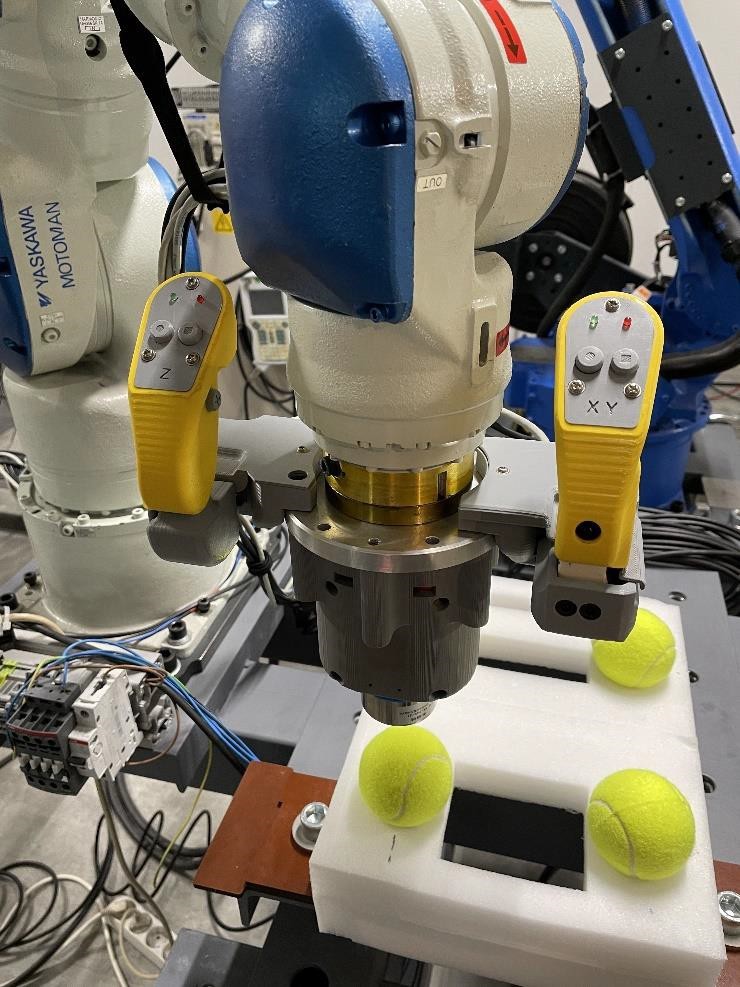
We had a first approach with the digital shadow. One student was controlling the robot with the controller with the objective of touching different targets (tennis balls in our case) while another student was looking at the 3D model in Unity. The 3D model would follow the movements of the physical robot.
The tennis balls were also modeled in Unity and would turn red once the robot touched them, this was made possible thanks to collision detection. When a ball was touched the next one appeared. After touching the last ball, all four balls appeared on display. We then could reset the balls and repeat the task.
The code:
All of the code was written in unity scripts using C#. For communication between ROAC and unity, the UDP protocol was used. The robot control unit was connected to the PC using the switch. The same communication with a different class in C# was used for linking unity and RoboDK.
At any time, we could activate the functions of the digital shadow in unity, so our robot in VR can copy the movement of our physical robot.
As part of a demonstration the green virtual balls were created. When touched, they become red, and after a few seconds, they disappear. The physical representation of those balls were tennis balls, so we could really feel the contact and at the same time see the virtual contact between our robot and balls.
The robot can share a lot of data on different parameters but, for our purposes we only need the angles. We split the data and used the angles to change the position of the robot in unity or our physical model, depending on the data’s transfer direction.
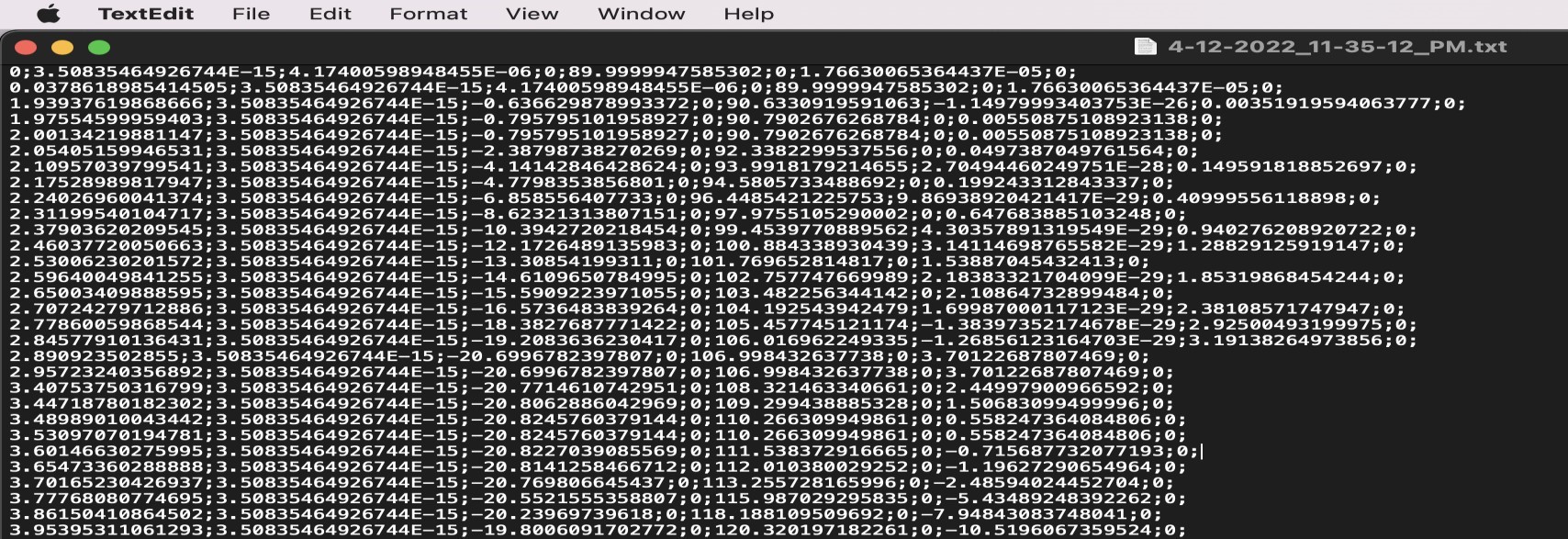
During the training of the robot, we can activate the record function, which we also implemented in C#. The function creates the text file that contains the time and angles of the points we recorded.
Here is the data structure: [Time of action]; Angle1; Angle2; …; Angle6; Angle7;
Example: 0.126567658; 23.59; 12.36; 45.55; …; 55.36; 28.98;
Afternoon session:
In the afternoon we headed back to the laboratory to see the movement of the robot using the haptic controller.
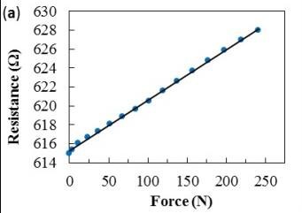
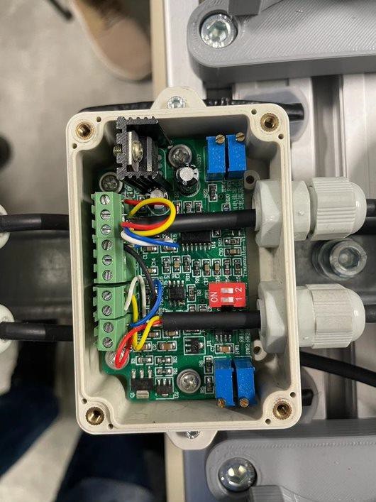
We were briefly taught how the haptic controller worked: they were strain gauges applied in a way to only be sensible to a directional force. Three of them were used to be able to sense forces along the x, y and z axis separately. After converting the difference in voltage of the strain gauge to its corresponding difference in force, these data are filtered and clamped using a capacitor and a resistor. Since the signal coming from the sensor is about a few millivolts the device amplifies the current intensity and filters the signal cutting the non-important frequencies. This way the signal can go to the motherboard in order to be processed.
This is done using the component on the right.
We then translate this signal to a difference in position and send this filtered data to the physical machine, which then applies the relative movement.
We must note that the sensors of the different axes have different payloads. In our case, the z axis had a higher payload and was much harder to move than the other.
This is a diagram explaining the operating method of controlling the physical robot using a remote controller:
We then translate this signal to a difference in position and send this filtered data to the physical machine, which then applies the relative movement.
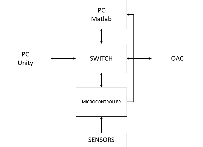
We can see an additional use of Matlab, which consented us to optimize our movements and trajectories.
We then had the opportunity to see the digital shadow and the digital twin in action.
For this session we interacted with both the real robot and the 3D model using 3 different ways to make them move: Mounted joysticks, remote joysticks and VR controller. We also had 2 ways to visualize the robot’s moves: On a 2D screen or in VR.
Every time the task was to press tennis balls (real or virtual ones) as quickly and precisely as possible.
First, we tried to make the 3D model move while wearing an HMD and by using VR controllers. We were able to get fast and precise movements but occasionally the 3D model motion was erratic. Still, we were able to reliably touch the tennis balls.
Then, we tried to make the robot move with the mounted joysticks. They were designed by the professor and they are 3D printed. By design, it’s important to decouple the forces applied on the robot to avoid any problems. To do that, they implemented three strain gauges. One on the left side and two on the right side. The left joystick is dedicated to Z axis movements (up and down). The right one is dedicated to X axis and Y axis movements (forward/backwards and left/right respectively). Two buttons are located on the back of the joysticks. When pressed simultaneously the robot is activated and is able to move. The system stops if you release at least one of them. Two other buttons are located on the front of each joystick. The ones on the left are used to record target points, the ones on the right can record trajectories. They can also be programmed to do whatever is needed. Finally, there are 2 side buttons that can be programmed if needed.
To use the joystick controllers, you first need to press the two back buttons. Then you need to apply a slight force in the desired direction without showing resistance to the robot’s movements. The left joystick is less sensitive because its strain gauge requires twice the force to achieve a similar deformation (10 kg vs 5 kg)
As intended, the 3D model would follow every move of the real one.
Following this, we saw a demonstration of the remote joysticks and although they are a bit unpractical, paired with cameras they could allow someone to do remote work with ease.
Finally, we had a glimpse of the future of this industry: The digital twin. Using the VR headset and the VR controllers, by controlling the 3D model in unity, we were able to make the real robot move and accomplish a task. However, with the current state of the simulation it’s not recommended to use the system this way. The system actually, doesn’t have enough securities which can with any bug, misuse or create accidents.
JLL DAY 4
Morning session:
Objective:
- Finish writing the weekly report and final group presentation
In the morning we had a full report writing and teambuilding session. We divided the whole program into multiple parts and assigned an individual one to each team member. Everyone worked on their individual part whilst discussing and helping each other.
In the lab, we all had to take part in an experiment. We were assigned a task that consisted in touching four balls with the robot in a specified order and record both the trajectory and the target points when in contact with the balls. At first everyone was asked to do it by using the haptic controller, we had 2 tries. Then we were asked to do the same thing while wearing the VR Headset. After each session we were asked a couple questions to evaluate the performance of the system.
Afternoon session
- Manually teaching the robot the trajectories it has to perform using the different controls we had been taught in these days