Technological Cell - Geometric modeling
The ultimate goal of this student project is to realize key technological functions of programming a welding robot and its assistant through the XR-based HMI layer using the concept of Programming by Demonstration (PbD). Unlike the conventional PbD approach, which is realized through interaction with the physical system in the physical plane (kinesthetic movements through the application of appropriate interfaces), here programming is realized in the virtual space of the digital twin, that is, a new concept XR PbD is realized. When the training of robots is realized in a virtual space, then the coded task is transferred to the physical robots in the technological cell and thus enables the reliable execution of the set work task. In order to practically realize the XR PbD concept, it is necessary to provide a number of process building blocks:
- control of robot movement in virtual space using a physical haptic device
- recording of realized movements and their optimization by subsequent processing
- verification of optimized movement through simulation (playback mode),
- transfer of optimized and verified movement to the control system of the physical robot,
- verification of optimized movement on the physical system by simulation and
- execution of the work task.
All of this being said this project will be divided into three steps:
- STEP 1: Construction of a geometric 3D model of the technological cell, using SolidWorks 3D CAD modeler and input information that is part of this project task or additionally defined by instructors working with students.
- STEP 2: By adding kinematic features, transform the 3D geometric model into a 3D kinematic model, with interactions that include: interaction with the virtual digital model and interaction with the physical entities of the technological cell.
- STEP 3: By further extension of the formed 3D kinematic model, connect it with the selected XR Engine and with the use of selected XR headsets form XR-based HMI layer for immersive human interaction with the physical technological cell - Hybrid system for collaborative robotic assembly and welding, and its digital replica that is, manufacturing digital twin.
Only the first step will be elaborated below, as it is the topic of this document.
Workflow Description
Construction of a geometric 3D model of the technological cell, using SolidWorks 3D CAD modeler and input information that is part of this project task or additionally defined by teaching assistants.
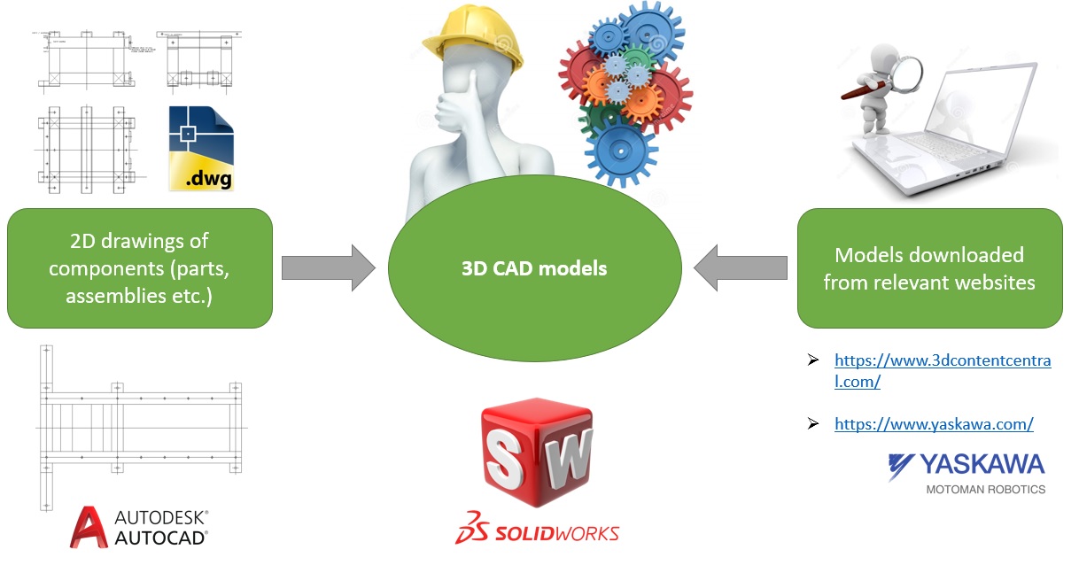
Main job here was to find or get from our teachers 2D drawings of parts, assemblies and create 3D geometric model from that drawing. For complex parts and assemblies (example: robot arm, controllers, etc.) models were searched on the internet, on reliable websites. Also, part of the job was to find any open-source data sheet, technical documentation or drawing of robots (MA1400, SIA10F), controllers (DX100, FS100), additional parts, etc. But this will be explained in detail below.
Multimodal interaction of Human with the (factory) environment
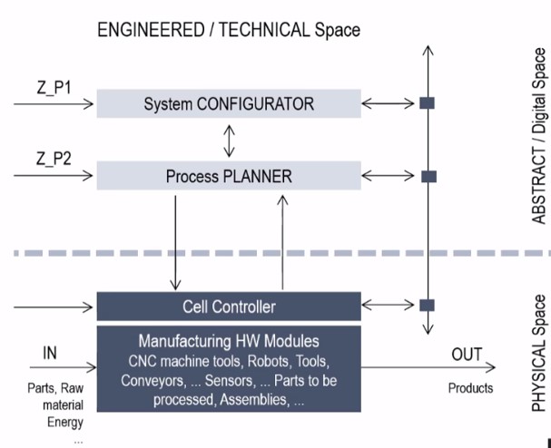
Let’s start with a typical manufacturing environment composed of manufacturing hardware like CNC tools, robots, conveyors, sensors, assemblies, etc. all together well known for all of us and there should be another layer related to the control aspects that we call cell controller. So, it is a physical space of our complex manufacturing environment.
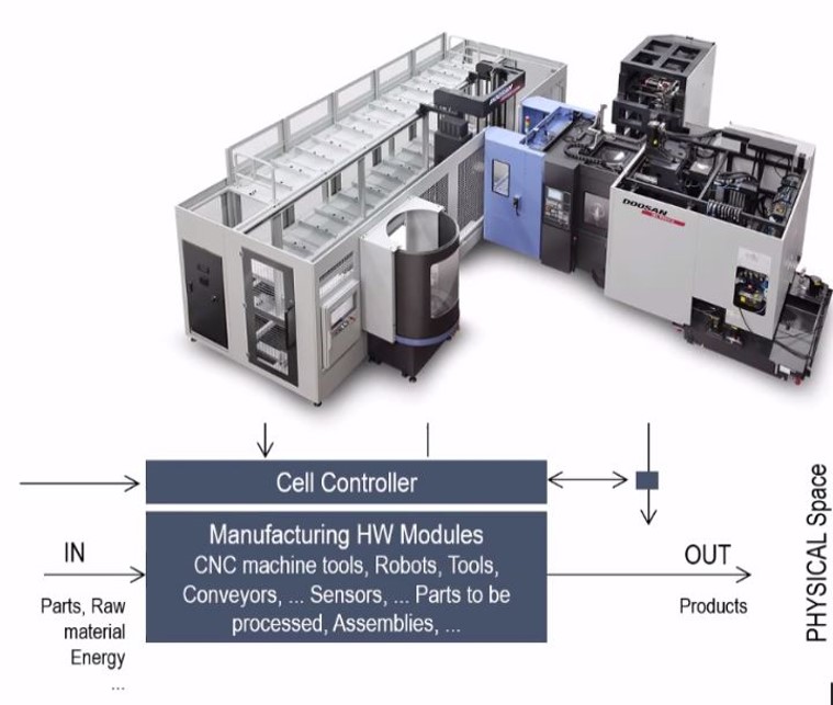
We are living in the age of ICT technologies, so we have another layer, abstract/digital space. Inside we have an equivalent system, a virtual system for configuration for manufacturing: process planning, connections to the other factory subsystems, etc. So, there should be two layers: physical and abstract. All together we call it technical subspace or subspace with engineered entities.
A general consideration on Computer Aided Design (CAD) Systems
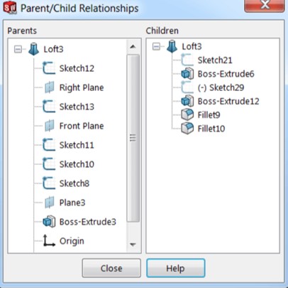
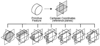
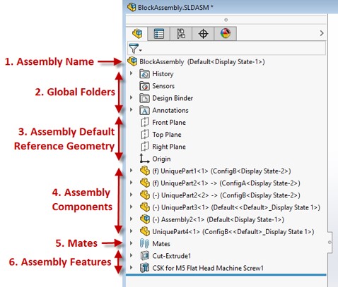
Modern 3D Computer Aided Design (CAD) Systems are PARAMETRIC MODELERS Parametric modeling systems rely on DATA STRUCTURES that maintain three-dimensional information on specific aspects of the model – parameterized FEATURED, organized in an associative manner – PARENT / CHILD. Features in the model are CONNECTED HIERARCHICALLY, creating a network structure where every node represents a FEATURE and every connection represents a DEPENDENCY between two features. This structure is commonly known as DESIGN TREE feature tree, or history tree.
When FEATURE DEPENDENCIES are properly defined, ALTERIONS performed to a parent node will automatically propagate to its child nodes i.e., the CAD model will REACT to CHANGES (of parameters) in a predictable and usually stable manner.
In short, parametric modelers mean that complete data structure describes the geometry, the topology of parts we want to design is organized as a hierarchical structure, and all elements in this structure are defined by parameters, so we can change what we want, to optimize the design, aspects of the path we want to create.
The same holds for assembly which is a practically ordered set of parts we already created one by one. In this aspect, it is important to find the position of any part in the assembly, and we can do this in two approaches: the first one is by explicit definition which is very rigid and the other one is kinematic joints where we can establish some kinematic relations between parts which are present in our assembly.
So, we have a hierarchical data structure with kinematic relationships inside, constraints, and other aspects, and everything is parametrized. This is very important to be emphasized. We have to remember that the parametric geometrical model of any mechanical structure with some dynamic contents inside which means that we can change it according to our needs.
Description of preparatory installation activities and managing of settings for the SolidWorks CAD package 1.1
SolidWorks is used to develop mechatronics systems from beginning to end. At the initial stage, the software is used for planning, visual ideation, modeling, feasibility assessment, prototyping, and project management. The software is then used for design and building of mechanical, electrical, and software elements. One of the latest software is SolidWorks 2020 and it will be used by AVATAR UBelg team for regular modeling, developing kinematic model and developing interactive model based on SolidWorks API SDK. The SolidWorks API (Application Programming Interface) is a Component Object Model programming interface to the SolidWorks software. The API contains hundreds of functions that you can call from Visual Basic (VB), Visual Basic for Applications (VBA), VB.NET, C++, C#, etc. Specially here, Visual Studio 2019 will be used as IDE for C# programing language. By using SW API, we can bypass 3D CAD Modeler HMI (regular SW user interface) and connect directly to the 3D CAD Modeler Geometric Modeling Kemel. This means that pure engineering information that can be appropriately visualized (interface to human visual perceptive system) and manipulated in order to be upgraded or optimized.
- SolidWorks 2020 hardware requirements are:
- Processor: 3 GHz or higher clock speed (preferably closer to 4 GHz)
- Operating System: Windows 10 64-bit
- Memory: 32GB (16GB minimum)
- Hard Drive: Solid State Drive (SSD), maintaining at least 20GB free space
- Graphics Card:** Standard assemblies: NVIDIA Quadro P1000 or AMD Radeon Pro WX 4100 Large assemblies with simple parts: NVIDIA Quadro P2000 or AMD Radeon Pro WX 7100 Large assemblies with complex parts: NVIDIA Quadro P4000/5000 or AMD Radeon Pro WX 8200/9100 SOLIDWORKS Visualize 2020: NVIDIA Quadro P4000/5000 or AMD Radeon Pro WX 8200/9100
- Internet Connection:High speed broadband connection for downloading service packs
Short instruction for installation SolidWorks 2020:
-
Before installation, check if .NET Framework 3.5 and 4.0 are installed. If .NET Framework 3.5 (including 2.0) is not installed, go to “Control Panel” -> “Programs and Features” -> “Turn Windows features on or off” -> -> select “.NET Framework 3.5 (including 2.0)” -> select “.NET Framework 4.0 “ it can be different subversion (example: 4.8)
-
Install SolidWorks 2020 (including PDM Client if required). // it is important to choose folder different from one where SolidWorks 2018 was installed (it is usually installed in folder: /Program Files/SOLIDWORKS Corp)
1.1 If the System Check Warning window appears, ignore it (click Next to continue)
1.2 If the warning “SolidWorks Serial number was not found in activation database” appears, ignore it (click OK to continue)
1.3 If the full list of SW products to install is not visible, click “Select different package” and tick option “Select products not included in this package”
1.4 Select SolidWorks products to be installed
-
REBOOT COMPUTER! //restart computer
-
Run SolidWorks > Help > SolidNetWork License Manager > License Order //optional step
Use the “Move Up” and “Move Down” buttons to position Premium products with the same name higher than Professional and Professional products with the same name higher than Standard products
Click “Apply” to save the settings
Click “OK” to close the SolidNetWork License Manager
Task setting of Hybrid system for collaborative robotic assembly and welding
This is a hybrid system for collaborative robotic assembly and welding:
Assembly of weldments is very common and widespread in modern industrial production. It is one of the basic manufacturing technologies. A typical product of this class, a welded assembly, consists of a large number of components made of sheet metal or profiles of circular or square cross-section. Usually, one of the parts, the largest, is the basis for further construction of the assembly and it should not be forgotten that the assembly process is additive. The formation of the assembly, depending on its topology, takes place by sequential or parallel addition of parts. After relative positioning, each added part is fixed by welding, which retains the achieved position and also allows load transfer, which is very important and thus a topic of extensive research.
Manual arc-welding, as the name suggests, requires a human being in the center of the welding process where the weld is much dependant on the worker’s skill and knowledge. This in itself holds a few possible problems and safety hazards.
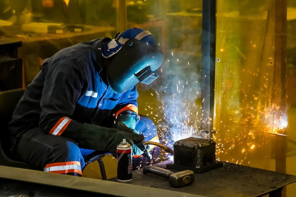
Companies need to invest time and money in educating their workers to keep safe instructions in place in the workplace. It is now clear why it is much better and safer not to expose the worker directly to this kind of work, but to use such a robotic cell. In that way, the welding job would be done much safer for people, but also of better quality. Also, it is not necessary to mention whether robots will replace humans. It is indisputable that the reader of this article will at least think that such a thing is not possible, because behind all this is a huge human job. Let us now return to the subject.
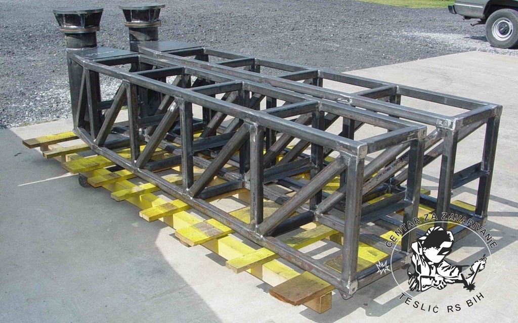
Modeling of the supporting structure of the technological cell
The supporting structure of technological cells consists of:
-
a platform, which is a basic component and has the task to geometrically and mechanically integrate all other parts of the supporting structure, to fix the supporting structure to the ground and to perform the leveling function
-
a bench that carries the welding robot,
-
the construction of a workbench for assembly and welding
-
the support of the assistant robot.
The supporting structure is made as a welded assembly, using standard U10 profiles and steel profiles with a square cross section of 100x100mm. As input information, we obtained 2D drawings of all components of the supporting structure of technological cells.
We got familiar with the 2D sketch in AUTOCAD that was provided to us by the professor. The sketch included subassemblies of the bench for the robot and the desk bench as well as the stand of the two robots. This base consists mostly of standard U-profiles and square-profiles. The modeling stage began with the extruding of mentioned profiles to the required lengths and cutting necessary holes in them. The other parts, such as hex nuts and screws were downloaded from the following websites: https://grabcad.com/, https://product.item24.de/, seeing they are standard parts. The nuts that were required are M12, M16, M24 and for the screws it was M16. The next step was assembling the base. The welded mates were not added to the 3D model, even though they are shown in the 2D sketch (that includes the nuts that are welded to the profiles).
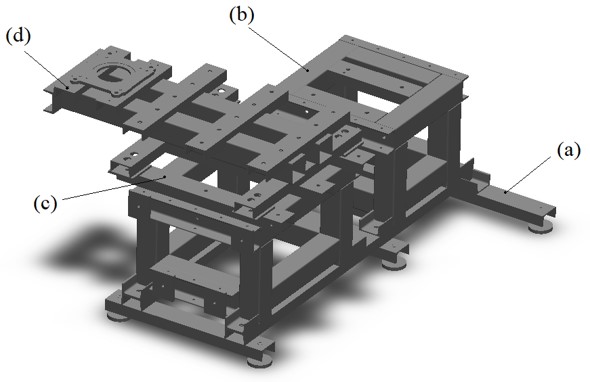
- a) a platform
- b) a bench
- c) the construction of a workbench for assembly and welding
- d) the support of the assistant robot
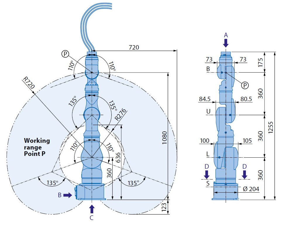
Modeling robot welder – MA1400
MOTOMAN – MA1400 is 6-axis robot that is used for arc welding. Besides arc welding, this robot can also be used for: Laser welding, MIG welding, plasma welding and TIG welding. It is built for achieving optimal results in difficult and conditions. With its superior wire feed system, the maximum working range of astonishing 1434 mm and integrated media hose package, the 6-axis robot MA1400 significantly improve welding quality. The torch cables are integrated in the robot arm in order to avoid collisions with the work piece or other robots. Our robot will use DX100 controller.
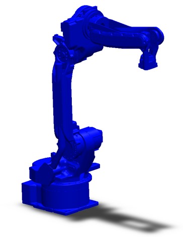
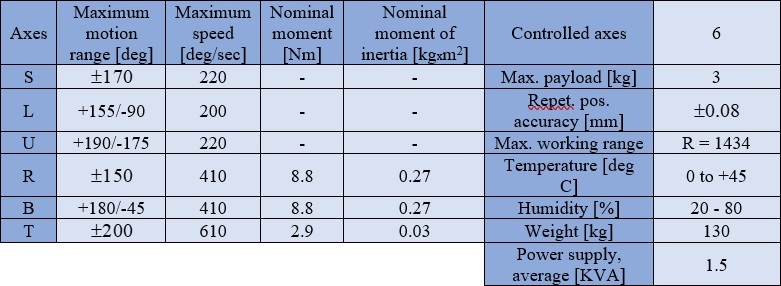
The fastest robot in its class, the MA1400 Motoman welding robot features cutting-edge motors and ARM control. The Sigma V AC servo motors allow for advanced control that significantly reduces welding cycle time. A 3 kg payload and generous 1434 mm reach increase the productivity of the Motoman MA1400 DX100. There are modern versions of this robot: MA1440 and AR1440. This new generation of robots has been optimized in terms of mechanics and control, but the concept has remained unchanged (thru-hole concept of the final segment of the robot is the same). We can summarize all benefits of this powerful robot extracted from the table above:
- Enlarged welding reach (1434mm)
- Can be used for welding of short as well as welding a very long seams
- Protected cable routing in the robot arm (shown in the picture below)
- Simple machining of bulky and hard-to-access workpiesces
- Increased productivity
- Production space savings thanks to high density of robots in cell
- Increased productivity with very fast dynamics
- Space-saving cell concept
Three types of mounting are available for this robot: floor-mounted; wall-mounted type and ceiling-mounted type. Type we used, as previously explained, is floor-mounted type with base.
As our task is to provide 3D model of robot MA1400 in SolidWorks, it was downloaded from https://www.3dcontentcentral.com/ website. Its data sheet with necessary technical drawings was downloaded from Yakasawa’s official site: https://www.yaskawa.com/. In this step only 3D model was done with no kinematic feature added. Kinematics will be covered in the next step. CMSysLab has one robot Yakasawa MA1400 and that is reason why this robot specifically was chosen in this project.
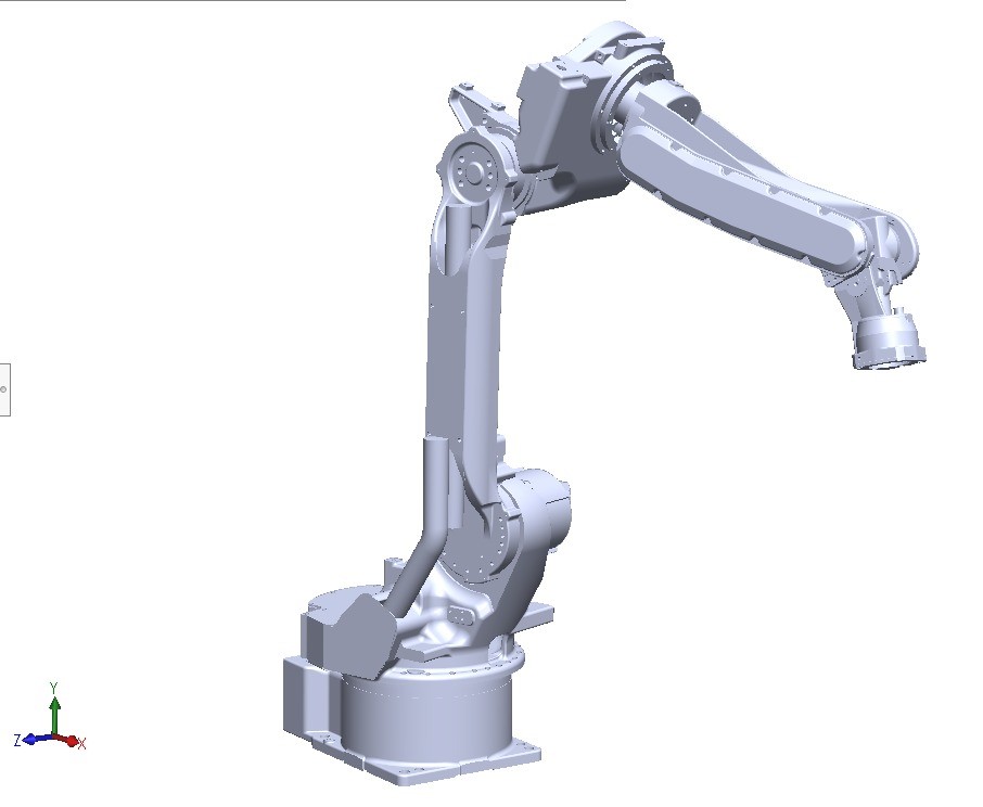
Modeling of the robot assistant
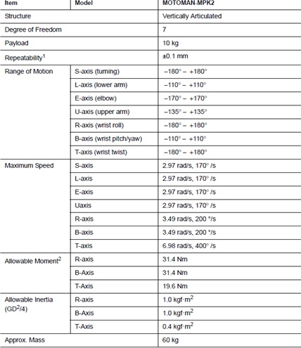
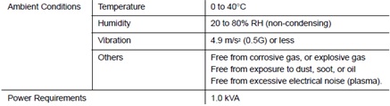
For the robot assistant, we are using SIA 10F YASKAWA redundant robot arm with its control system FS100. This robot is a 7-axis robot, and it has fascinating performances such as providing „human-like“ flexibility of movement and enormous speed (1ms in all servo-loops, which leads this robot to the list of most capable and flexible robots in the market). This robot offers a high payload (10kg) and big working ranges.
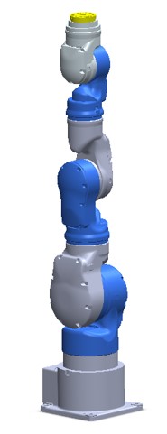
The agile and versatile robot opens up a wide range of industrial applications to robots: ideal for assembly, injection molding, inspection, machine tending and a host of other operations. This robot is intended for performing operations of manipulation of welded parts and dimensional metrology operations (scanning the geometry of the assembly which will be welded, primarily joints of assembly, as well as determining the location of the assembly to be welded in the working space of technological cells). Installation in narrow spaces between machines is possible with this type of robot.
- Performances One of the most important attributes of the robot arm is flexibility. The seven-axis configuration has enabled the angle of the elbow to be changed without affecting the tool position or posture. The arm’s flexibility enables the SIA robot to be installed in a high-density layout without interference and to enter narrow spaces inaccessible to humans. The SIA robot can be installed in many ways without affecting functionality: on the floor, wall, or ceiling. Basic specifications are shown in the following picture, which is taken from the datasheet of the robot.
Welding system modeling and welding robot installation
In this part we are implementing required welding equipment. In the following picture will be shown all parts.
- Wire Feeder DT400_OK
- Winding of wire
- Blowtorch - ESAB 220i PLUS
- Welding tool - Binzel Segment Holder Abirob A300 ECO
- Argon gas container
- Cooling unit
Formation of variant dispositions of the equipment (layout) of the technological cell
 Variant 1 Variant 2
Modeling and installation of Control systems for robots
Our robot assistant uses FS100 control system. This control system is specialized for picking and packing sectors. This controller has the following performances: real-time processing of sensor signals, reactions to camera information and other high-speed applications. It is great for the environments, where high flexibility is required. One of the new features is the open concept of the controller. This means, that users can access the robot interfaces and motions externally (via PC or PLC) and also develop their applications. This controller can be used as a slave of the higher-level controller. One of the important characteristics of this controller is that it can be combined with the high-performance DX100 controller for executing our task in this project, welding.
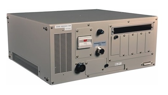
FS100 Controller
Key features of the FS100 Controller:
- 2-4 times faster than DX100 controller
- Designed for packaging and small parts handling robots with payloads of 20 kg and under
- Compatible with integrated MotoSight™ 2Dvision (optional)
- Improved communication speeds and functionality
- High-speed I/O response and high-resolution timers
- Supports a wide range of communication networks
- Single controller supports up to eight axes:
- 4-axis robot + 2 external axes
- 6-axis robot + 2 external axes
- 7-axis robot + 1 external axis
- 15-axis robots require two FS100 controllers
On the other hand, DX100 is the control system for the robot welder. One of the main characteristics is that dynamic interference zones protect the robot arm and provide advanced collision avoidance. Fast processing speed leads to smooth interpolation. DX100 control cabinet allows for up to three external axes and they can be remoted.
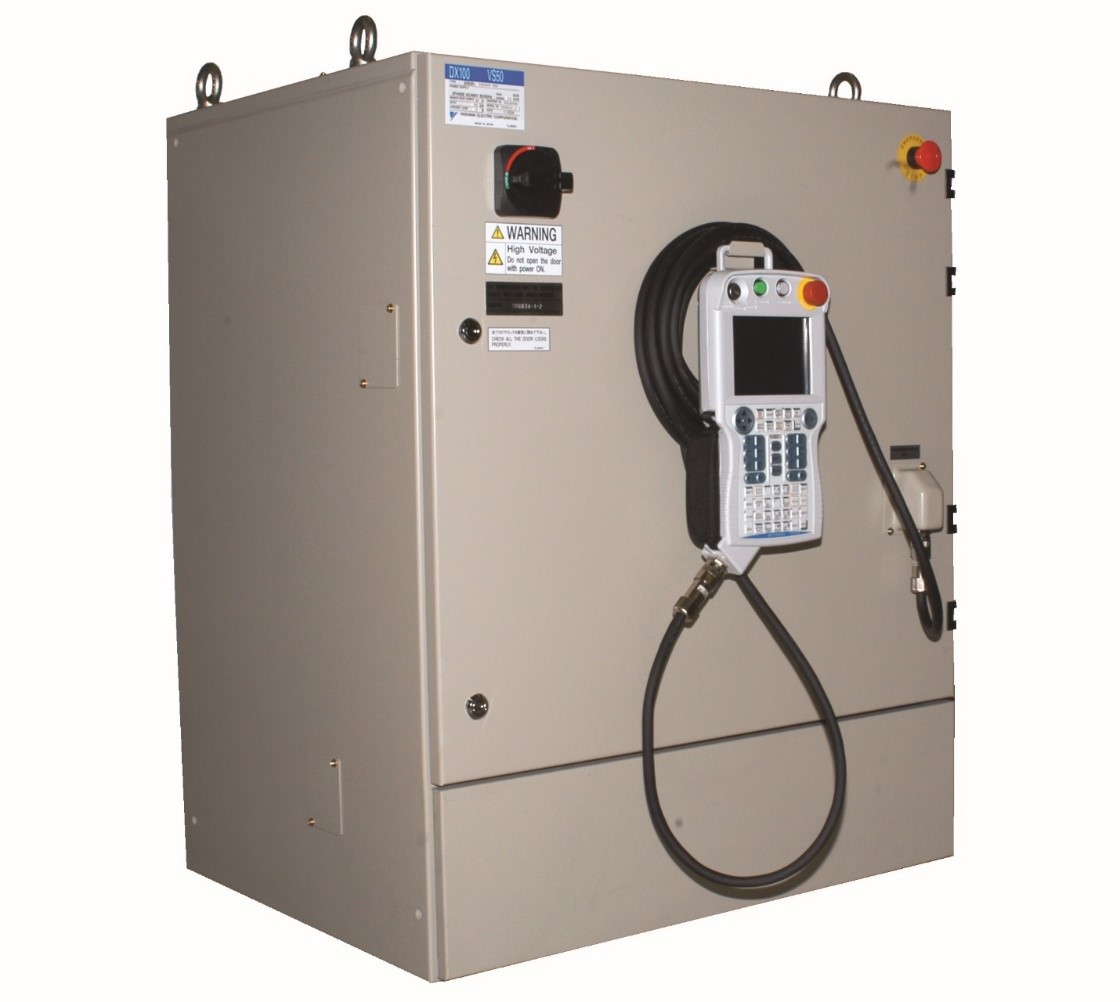
DX100 Controller
Key features of the DX100 Controller:
- Patented multiple robot control (up to 8 robots, 72 axes)
- Faster processing, high performance
- Integrated cell control capabilities
- Open communication
- Energy savings
The control system DX100 and FS100 ware downloaded from https://www.yaskawa.com/. The 2D sketches and 3D models, as well as the pdf file of the technical documentation was acquired.
Modeling of input and output conveyors
Conveyor is a mechanical apparatus used for moving articles or bulk material from place to place (as by an endless moving belt or a chain of receptacles). This part was made from the acquired documentation.
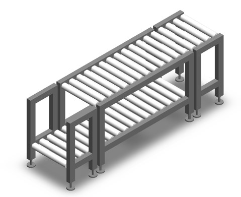 3D model of conveyor
Modeling and assembly of protection and dedusting system
Dedusting system is very important part of working ambient. Welding facilities are very hazard environment in terms of sawdust that produces. This sawdust can reduce machine life exponentially and make maintenance of machines difficult. The purpose of dedusting system is to intake that dust and remove it from working environment Model used is provided by teachers of AVATAR UBelg group and it is shown on the figure below.
 3D model of dedusting system
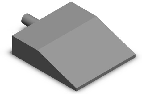
Modeling of a workpiece
There are two models of weldments. The first consists of a plate, a bent U-profile, and a classic U-profile.
 3D model of weldment 1
The second weldment consists of a corrugated metal sheet and rectangular profile.
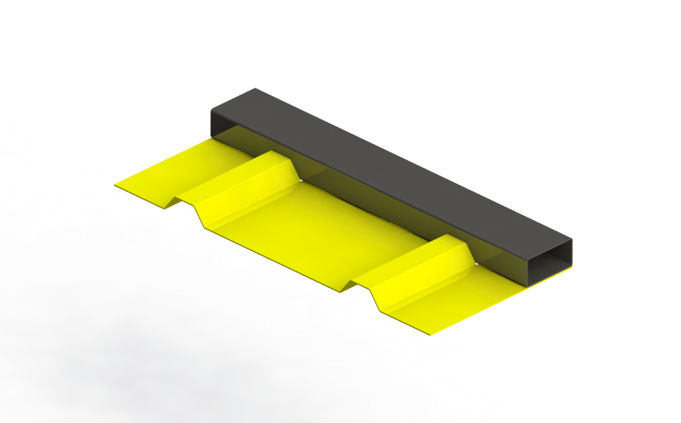 3D model of weldment 2
Results
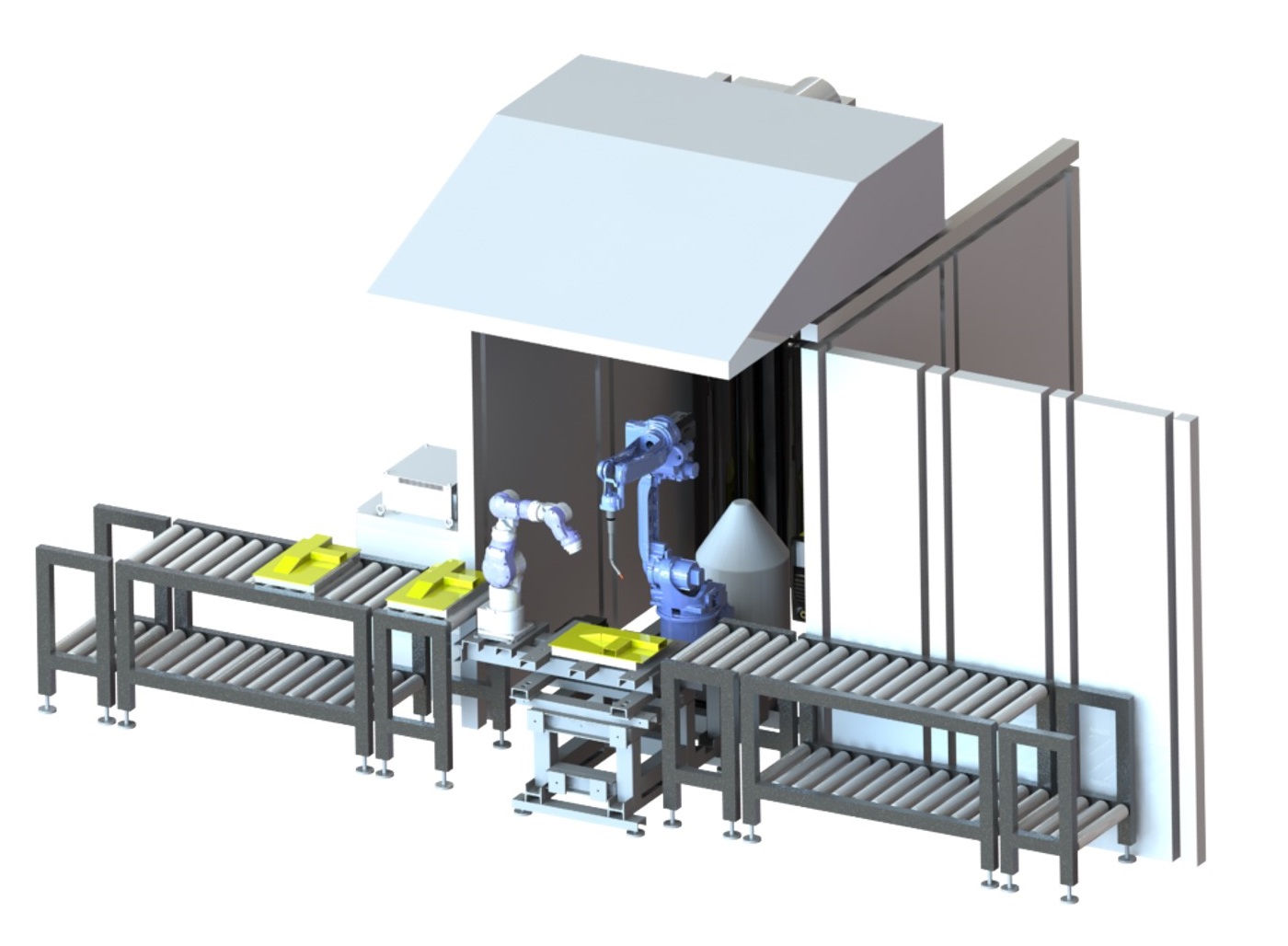
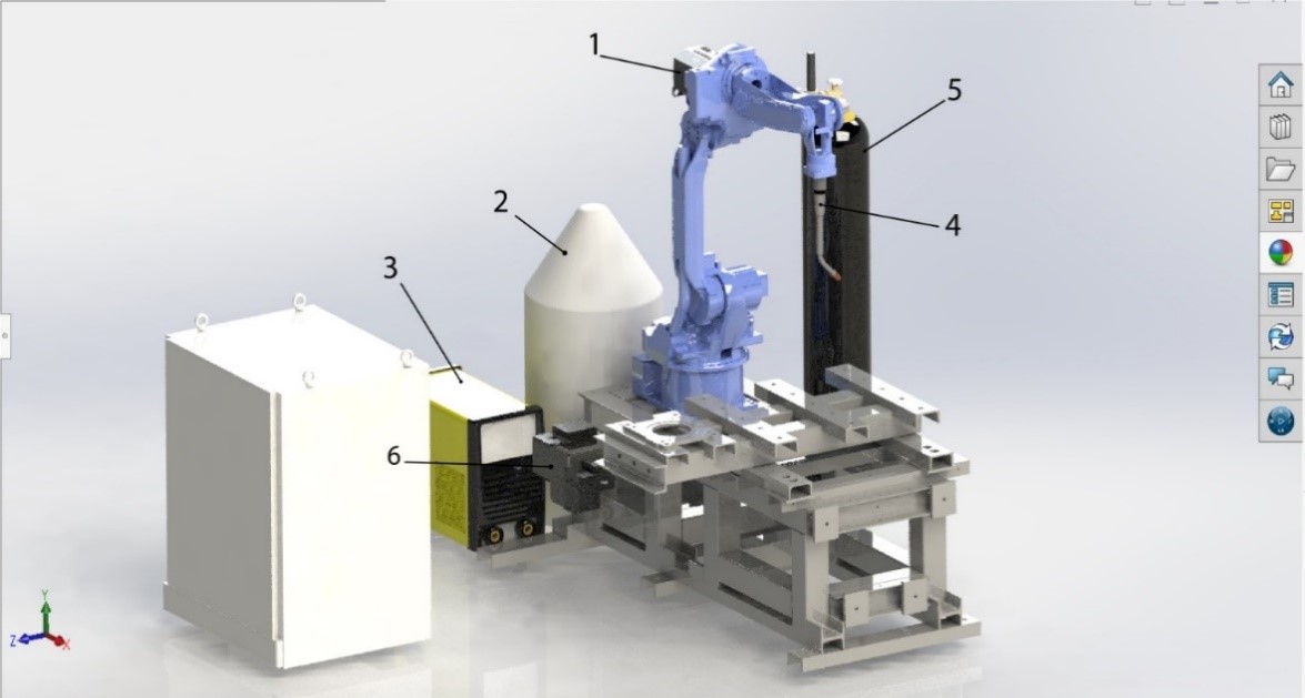
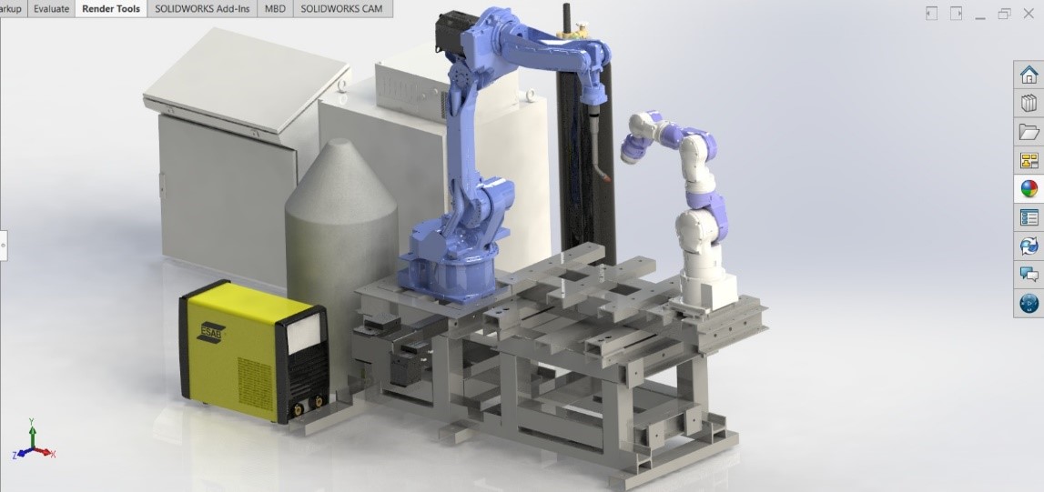
The results of our work were making a 3D model of a functional robotic cell, that is shown in the following picture.
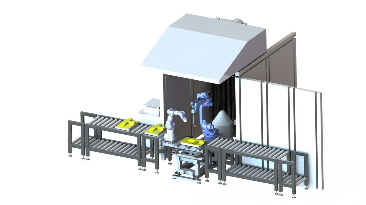 3D model of functional robotic cell
Hybrid robot cell for collaborative assembly and welding consists of the following subsystems:
- robot welder -specialized industrial robot for arc-welding tasks, YASKAWA MA1400 with DX100 robot controller
- robot assistant –a redundant anthropomorphic robot with a load capacity of 10 kg with system management of open architecture, YASKAWA SIA10F
- supporting structure (frame) for supporting the robot and the work table on which assembly and welding operations are performed
- welding unit with cable set wire feeder DT400, Binzel welding torch, ESAB 220i PLUS welding machine, storage of wire, and argon gas tank added
- auxiliary accessories for positioning the welded assembly and gripper for gripping the parts to be assembled and welded
- conveyor system for introducing parts into the process and accumulation
- output conveyor system for transporting welded assemblies
- enclosure system
- cell controller with SCADA system and communication to higher levels of production process management.
Conclusion
In the end, we got a static structure. This is what is inherent in a geometric model. In the next step, which is not the topic of this presentation, we breathed life into that structure. It became dynamic, it started to move in accordance with the needs of the manufacturing process. Also, the digital twin must be a processually good replica of the physical twin. This passive structure although it’s parametric didn’t have functionality because it wasn’t dynamic and that was actually our next step.
Avatar for me
This project marked the semester of our studies. It was challenging, but we managed to overcome every problem we encountered with teamwork and with the help of professors and teaching assistants. When we compare where we were at the beginning of the semester, and where we are now with our knowledge and experience, we have a full heart. We learned teamwork, we learned to present well what we did in a foreign language, made friends within the team, and internationally and much more. This was a remarkable experience!