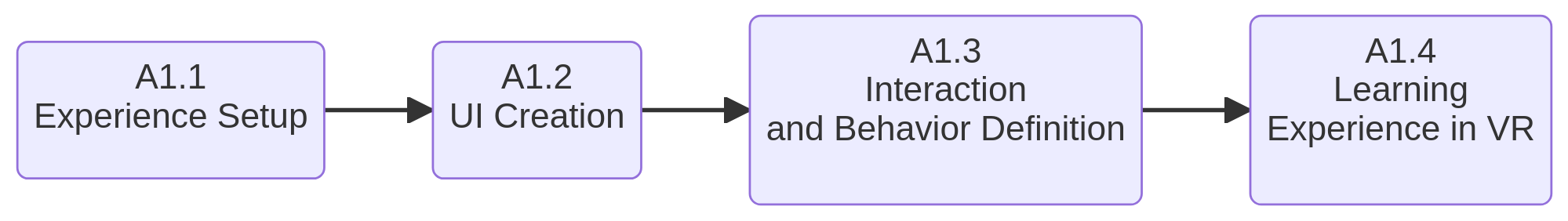
L1 - Assembling a Mechanical Component
The goal of this workflow is to show how to build an application for teaching students how a mechanical assembly works. Tho workflow makes heavy reuse of previous workflow defined in the project, combining them to obtain a full learning experience in an immersive XR environment.
 |
Assembly of a Mechanical Component Workflow
Workflow Building-Blocks
| Acitivities | Overview |
|---|---|
| A1.1 Experience Setup | • Description: he goal is to create a proper 3D environment to deliver the learning experience. The environment is built according to the workflow A1 - Scene Creation. • Input: 3D models of parts and assembly of the mechanical component and environment. • Output: XR Environment • Control: Model specifications - Tracking rate - Technical datasheets • Resource: XR hardware and software, technical specifications, docs and CAD modelers |
| A1.2 UI Creation | • Description: the goal is to enrich the XR environment with UI elements that support the task the VR environment is built for, i.e. explain how a mechanical assembly works. The workflow A4 - UI Creation has been used as reference for this activity. For this specific application, the bill of material and the technical drawing of the parts and assemblies are needed as visual element in the scene. 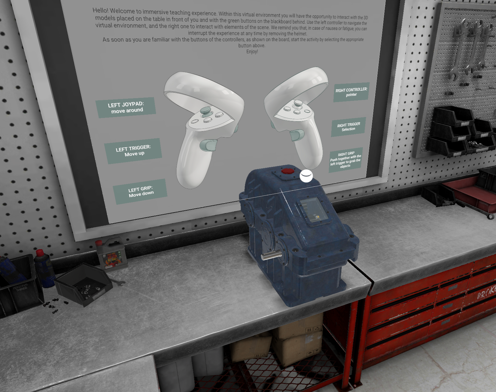 • Input: XR Environment, Bill of Material, technical drawings, visual elements (e.g. buttons). • Output: XR with UI. • Control: UI specifications and device capacity. • Resource: XR hardware and software, technical specifications and documentation, available assets and devices. 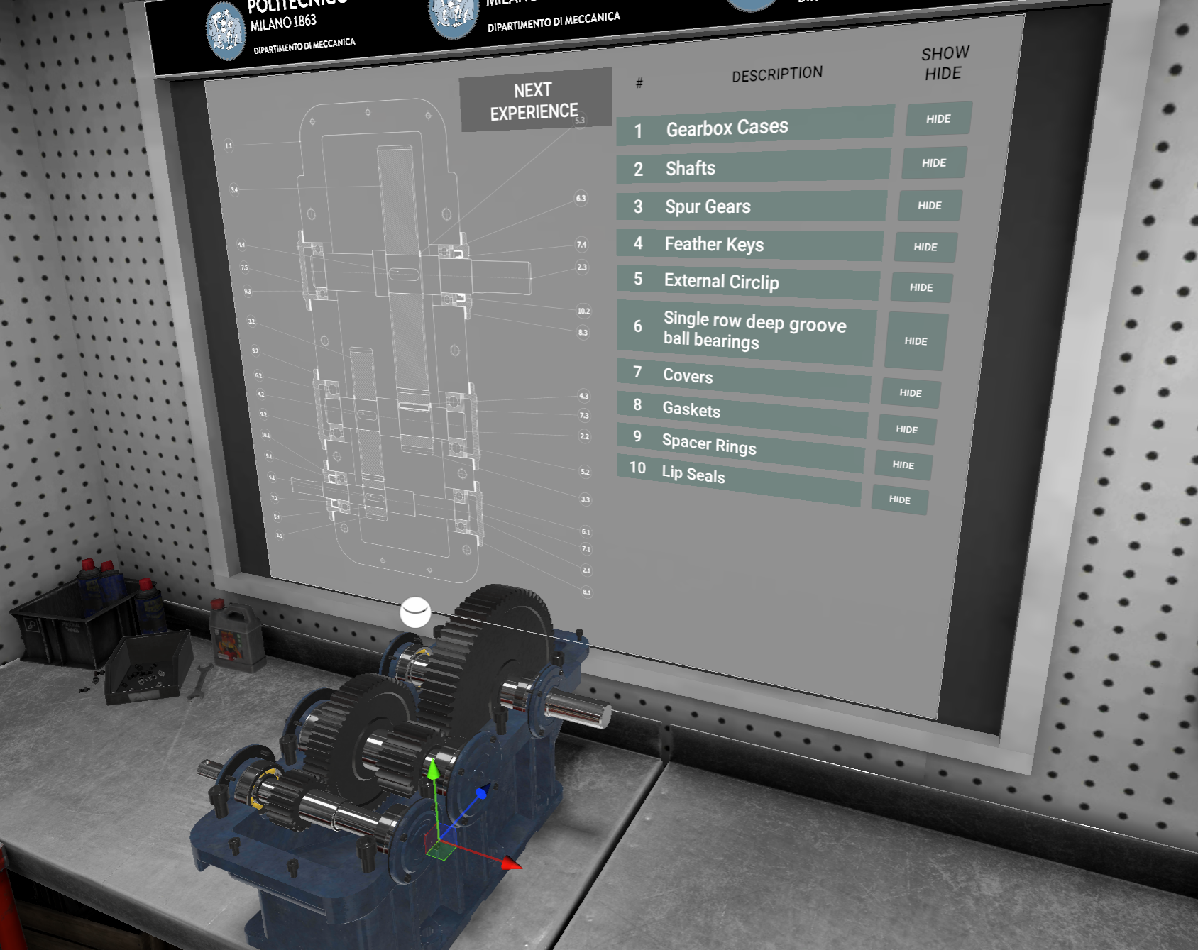 |
| A1.3 Interaction and Behavior Definition | • Description: the goal is to provide the XR environment and UI the capability to react to user input properly, following the prescription provided by the workflow A3- Interation. In this activity, the interaction modalities will be defined in terms of (1) which objects in the scene the user can interact with and (2) for each of the objects, which interaction modality is more suited. For example, which parts of the gearbox should be grabbable, how the user can interact with the BOM elements, etc. • Input: XR Environment with UI, assembly sequence and precedence diagram. • Output: XR Environment with interactions and behavior • Control: Interaction requirements, device capacity, expected behavior. • Resource: Expected behavior, APIs, Rendering system, Scripts. |
| A1.4 Learning Experience in VR | • Description: By using the XR environment with interaction and behavior, the students can actively use the VR application. The gearbox parts are grabbable and selectable and the student can disassemble the different elements of the gearbox with and without precendence constraints. The exercise aims at mimicking the real process of disassembly of the gearbox. While disassembling, the students can select the parts and check their name and technical representation on the blackboard behind the desk. The students can also explore the Bill of Material (BOM) related to the gearbox and the assembly drawing. • Input: XR Environment with interactions and behavior. While performing the procedure, if some step is wrong (e.g. violating a precedence) the application warns the user who cannot proceed until the step is done properly. • Output: text file logging the experience. • Control: trainers/professors supervising the learning process. • Resource: XR hardware and software |