A1 - Scene Creation
The SCENE CREATION workflow defines a set of activities that students need to carry out to create a 3D geometric model of an existing manufacturing system that is suited for the implementation as an Extended Reality (XR) environment.
The focus of the activities is not on the design of the manufacturing system itself, nor its subsystems or components, but on creating a 3D geometric model that must have:
- High geometric fidelity.
- High visual fidelity in terms of materials representation and shading (possibly avoiding artistic details that produce a large computational load).
Methodologically, SCENE CREATION workflow is based on a hybrid approach, i.e., a symbiosis of Computer-aided design (CAD) tools, for accurate parametric geometry modeling, and VR artistic tools, for creating a photo-realistic XR environment. The geometric model of the manufacturing system must be designed to enable further activities of students to create Digital Twin (DT) that integrate Virtual and Augmented Reality user interfaces (XR HMIs).
Workflow Structure
| CONTROL: Model specifications - Tracking rate and accuracy - Technical datasheets | ||
| INPUT: 2D part drawings - models library | 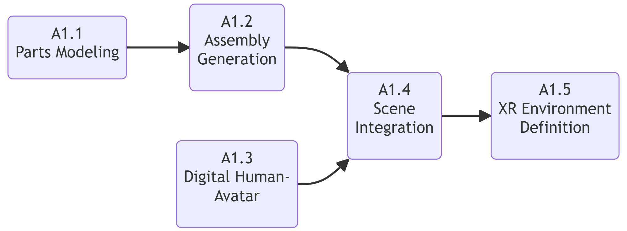 | OUTPUT: XR environment including user avatar |
| RESOURCE: CAD editor - 3D computer graphics - Rendering engine - XR Platform - Tracking system |
Scene Creation workflow
Workflow Building-Blocks
| Acitivities | Overview |
|---|---|
| A1.1 Parts Modeling | • Description: The goal is to create a collection of 3D models of all parts for each technological entity of the manufacturing system and understand their working principles. The steps to carry out are the following: 1) Generating the 3D models inside a CAD environment; two approaches are possible: • Download ready-made 3D models for standard elements and commercially available products (robots, machine tools, etc.). In this case, carefully check the rights of use from the provider. • Create a geometric model from scratch by implementing standard CAD features (e.g., extrude, revolve, hole definition, etc). 2) Specifying a consistent method for the reference point definition (i.e., the origin) of each atomic component with reference to each own bounding boxes (i.e., bottom, center, etc). 3) Adding basic colors, materials and textures. Since the created CAD model is parameterized, modifications are possible using the design tree. • Input: Bill of materials and processes. • Output: 3D parametric models of parts for all technological entities in a neutral interchange format (i.e., step, dxf, 3ds). • Control: Supervision and guidance by instructor. • Resource : 3D CAD modeling software (i.e., Solidworks), technical datasheets. |
| A1.2 Assembly Generation | • Description: Using CAD models of previously created parts, 3D models of assemblies of all technological units of the production system should be created by applying the following steps: 1) Create the assembly file in CAD modeler by importing and mating with geometric constraints the atomic components modeled in A1 according to a bottom-up approach. 2) The assembly creation sequence is recurrent, so previously created assemblies can be inserted as subassemblies into higher-level assemblies: This implies the organization of 3D assets according to a hierarchy of nodes based on the decomposition into elementary parts based on specific criteria (i.e., by distinguishing static and floating components to manage animations). This method also applies to 3D assets obtained from online resources: in this case, assemblies must be manually subdivided into elementary parts according to a top-down approach. • Input: Technical data of standard or commercially available equipment; 3D models of parts, access to the CAD models library. • Output: 3D parametric models of assemblies and subassemblies for all technological entities in a neutral interchange format (i.e., step). • Control: Supervision and guidance by instructor. • Resource : 3D CAD modeling software (i.e., Solidworks), technical datasheets. |
| A1.3 Digital Human - Avatar | • Description: Avatars in a virtual environment embody the user by providing a sense of self-localization, agency and bodily ownership. They also allow the user to interact with the environment and its elements. To track the user’s body and bring its movements to life within an avatar, the steps to carry out are the following: 1) Begin by setting up the body tracking and capture equipment, ideally in a large space where the user has freedom of movement. 2) Equip the user with all necessary gear to accurately track their body movements. 3) Stream the body tracking data to the XR environment for processing. 4) Import a 3D model of the avatar inside of the XR environment and integrates the user’s body tracking data. • Input: Tracking hardware (kinect, cameras…), 3D model representing the user and the user’s movements. • Output: Complete body tracking and full embodiment of the avatar in the XR environment. • Control: Tracking points, latency of streaming, avatar rig and behavior. • Resource : Capture Software and Hardware (e.g., Optitracking/Motive, Azure Kinect, Realsense), modeling software (e.g., Blender, Maya, C4D), XR development platform (e.g., Unity, Unreal), code editor (e.g., MS Visual Studio) |
| A1.4 Scene Integration | • Description: 3D models of parts and assemblies created in A1 and A2 must be defined according to a data structure that complies with the generation of an exploitable VR environment. This implies: 1) The choice of a compatible format for 3D models, since standard CAD interchange formats (e.g., STEP) cannot be imported in most VR development platforms, which only support mesh-based representations (e.g., glTF, obj). 2) A specific method for the scene configuration, that can be based on: a) An interchange file (e.g., JSON, XML, etc…) that embeds all the assets and scene properties, so that parts and assemblies can be configured as modular blocks (example here). b) The direct import of 3D models in the VR environment from a dedicated library. Further refinements can be carried out by fine tuning the position and orientation of the imported assets. c) The direct import in the VR environment of a super-assembly that already includes all the assets that will populate the scene in their default configuration, if that’s been previously exported in a single step from the CAD environment. In addition, geometric model of a human operator (AVATAR) can be inserted into the scene. The resulting scene assembly is static, yet fully parameterized, which allows its offline editing and modification, as well as real-time interaction between CAD modeler and VR engine if appropriate API-based Add-Ins and stand alone utilities are provided. • Input: 3D assembly models of technological entities, AVATAR geometric model • Output: XR scene populated by 3D assets. • Control: Supervision and guidance by instructor. • Resource : 3D CAD modeler and glTF/.obj exporter (i.e., Blender, add-In SolidWorks XR Exporter utility for .sldasm to .glTF conversion ), VR development platform (i.e., Unity), code editor (i.e., MS Visual Studio). |
| A1.5 XR Environment Definition | • Description: The scene file defined in A4 is ready to be processed and rendered with VR specific development tools. For this purpose, it is possible to further improve the visual quality of the 3D assets in glTF format by applying advanced materials based on the Physically-Based Rendering pipeline (example here), and by setting up the scene lighting. This operation can be carried out inside the XR visualization platform, or by editing materials in a separate environment that imports and exports mesh based 3D models (i.e., Blender). More details to make the XR scene exploitable by the user, (import drivers, libraries and classes for the selected HMD and associated control devices and set their parameters) are presented in the Interaction workflows and use cases. • Input: XR scene 3D model file. • Output: XR scene with fully operational HMD devices and improved visual appearance. • Control: Supervision and guidance by instructor; b) Verification and evaluation of produced outcomes; c) Written short report containing students’ experiences and indication of possible difficulties in their work, communication, and in understanding the task and the overall topic • Resource : XR development platform (i.e., Unity), PBR materials editing tool (i.e., Blender). |