JLL 2022 - Team 2
DAY 1
Objective: DIGITAL MODEL: CAD-based XR SCENE CREATION
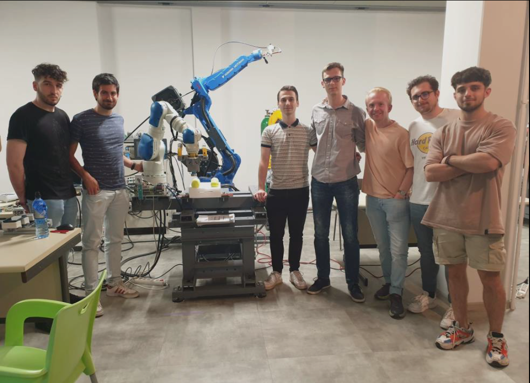
The first day of our Joint Learning Lab has been more a preparation for what is going to come in the following days.
The early morning has been spent in the lab presenting the three universities each other and presenting the project and its steps to all of us.
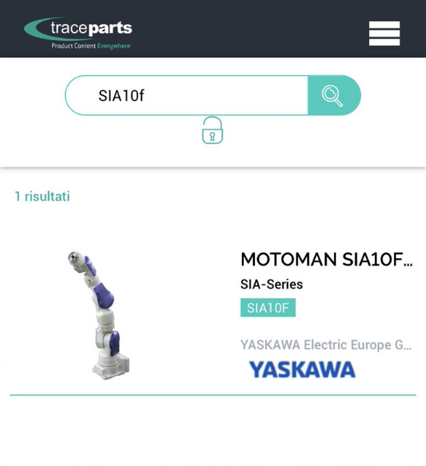
Once we have done with it, we moved to the computer room to start deepening in a practical way into the several stages to be tackled over the day. The first step has been the downloading of the CAD model of the robot we are working with from the site traceparts (link: https://www.traceparts.com/it). It is important to specify that we are working with a robot Motoman SIA10D but, unfortunately, this model is not available on traceparts so, we have downloaded the CAD model of the model SIA10F.
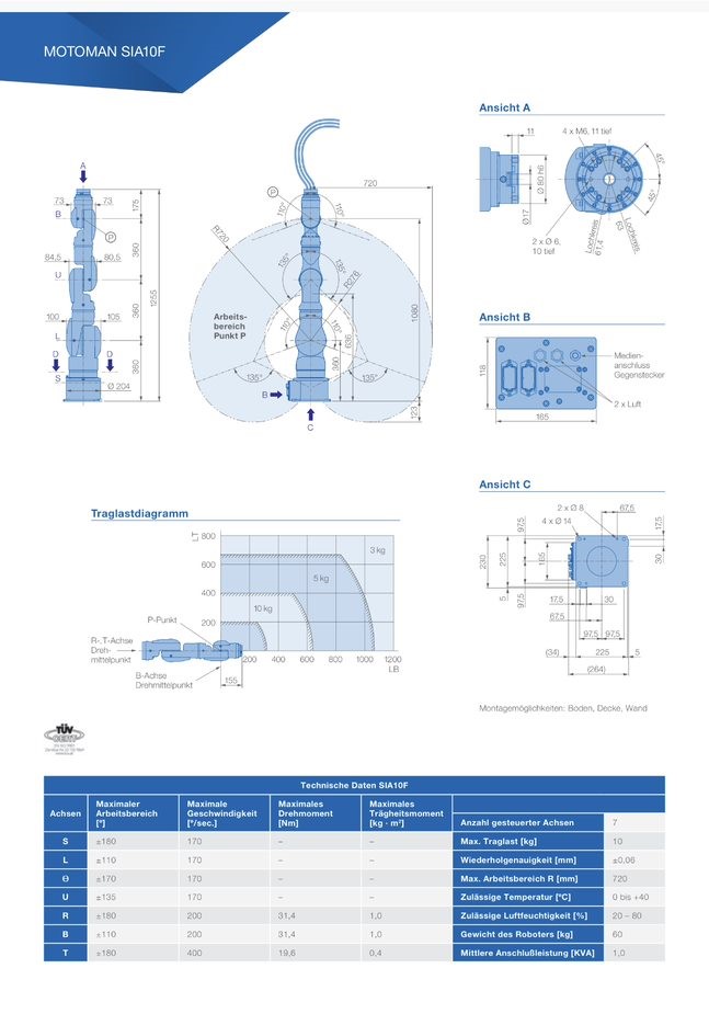
Once we had the CAD model on SolidWorks we had to check all its dimensions with the documents on the Motoman website regarding the model SIA10F to ensure that everything was correct because using a different model than the real one there could have been slight differences between those two models. In our case the difference is the end effector, in SIA10F it is 20mm longer so, we have had to adjust our CAD model.
After having adjusted the dimensions of the robot to make them equal to the ones of the SIA 10D robot, we had to change the reference frame of each joint of the robot. This operation has been done to study the kinematics of the robot. When evaluating the angle associated to each joint both in direct and inverse kinematics you need to have a reference system which allows you to understand what the relative rotation of each joint with respect to the axis of rotation is.
Once this operation has been completed, we exported the model into SolidWorks Visualize 2021 to convert the file into a GLTF one. The file has had to be opened on Unity but, to do it, we had to download UNI GLTF from the following link: https://github.com/ousttrue/UniGLTF .
On Unity we then imported the previously mentioned package to finally visualize it.
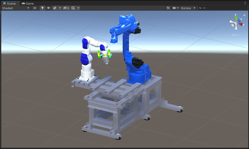
After having imported the 3D models in Unity, we experimented with Unity scripts and animations to get acquainted with the software and to prepare us for the next days of the JLL.
DAY 2
Morning session
Objective: XRSCENE ANIMATION - RWCKinematics Modeling
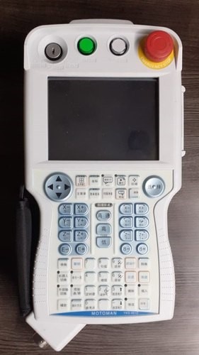
The starting point of Tuesday morning has been a general introduction on kinematics and on the main differences between forward and inverse kinematics. The difference was demonstrated using the teach pendant, which is connected to the robot controller. Also, we covered the basic principle behind creating a simple job task via teach pendant.
After that, we focused on coordinate systems, specifically on how to correct them for each joint of the robot because, each joint must have its own one in the right place to rotate properly in virtual reality.
The first objective has been to ensure a correct movement of the robot in Unity so, from the CAD model of the robot, we opened each part separately in order to check if the coordinate system (origin) was at the right place, at the centre of the link between this part and its “parent”. If it was not, we had to replace it and to export the part as a .STEP file (to define our new coordinate system as the origin), then to export it back as an .PRT file.
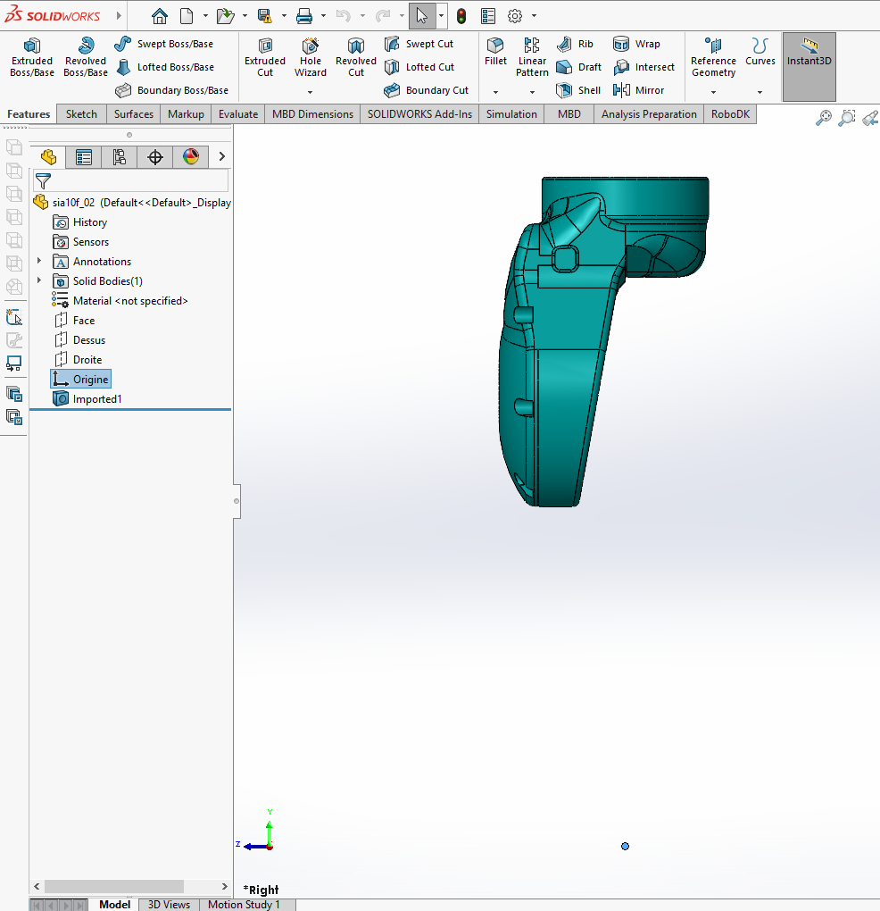
Example of badly positioned coordinate system
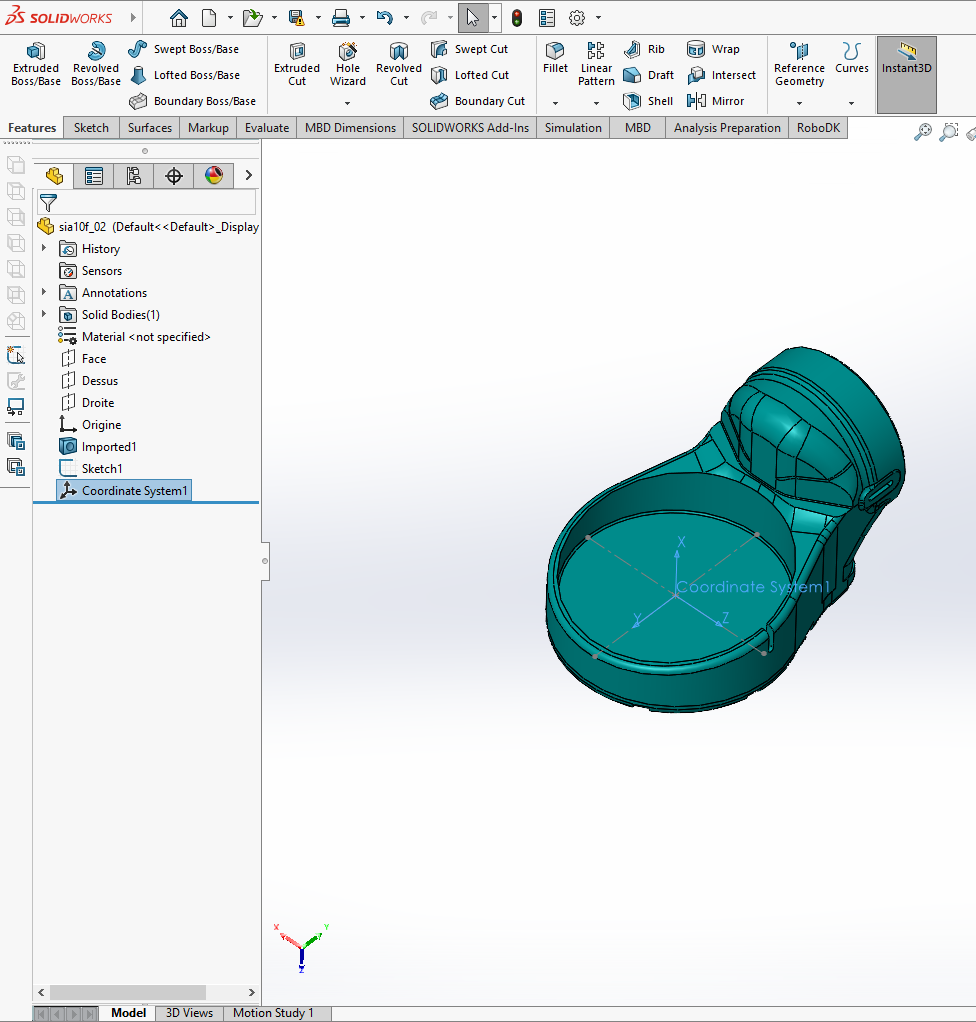
Example of correctly places coordinate system
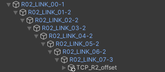
Then, in Unity, once all the coordinate systems of all joints were at the right place, we created the “parent – child” relation between each links, to allow the robot to move correctly (thanks to that, moving a certain part of the robot, all the following parts move with it as a rigid body). We just had to drag and drop each links (on the hierarchy) into the previous one.
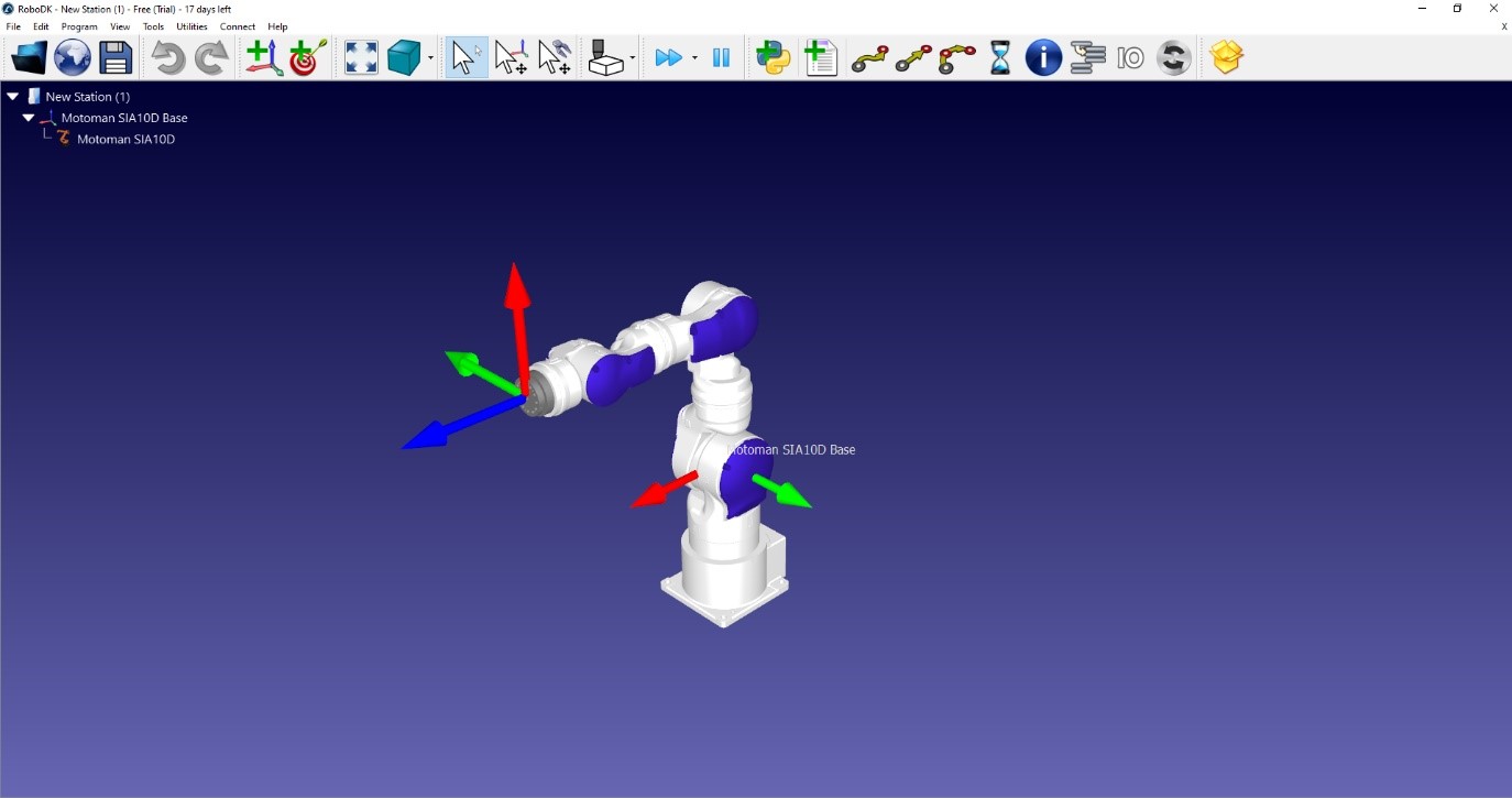
Then, we discovered the software RoboDK, which makes calculus for reverse kinematic. From the target position (coordinate) of TCP, it calculates a movement for each joint of the robot. It is the opposite of forward kinematic, which is when you manually move each joint of the robot, that makes the TCP move.
Afternoon session
Objective: XRSCENE ANIMATION - RWCKinematics Modeling
Topic of Tuesday afternoon session revolved around understanding and implementing HMD (Head mounted display) into our system. We had an overview of the different types of products available on the market (HTC Vive, Oculus Rift S, etc…). The technology differs between the models, for example, Oculus Rift S does not need any additional tracking devices that are needed to be placed around the room, everything is integrated in the headset/controllers.
To be able to integrate Oculus Rift S in Unity, Oculus Integration asset is needed. Assets could be found in the asset store of Unity (link: https://assetstore.unity.com).
Also, additional drivers are needed, specifically for Oculus Rift (https://www.oculus.com/rift/setup/)
The setup of the headset begins with defining the area of Oculus Guardian, which is used to keep the user in defined free area. Stepping close to the defined Guardian area results in showing the alarms to the user (red grids which correspond with the Guardian area). Passing the red grid turns on the cameras mounted on the headset, so that the user can see the physical world around him.
Finally, we have been able to step into the Unity scene which we created earlier. For now, the scene is static, so to start getting used to moving in VR.
Also, we went through the code that create a link between Unity and RoboDK. Unity sends a position and an orientation of the TCP to RoboDK (through a C# code). RoboDK then defines a precise movement (rotation) for each joint of the robot and sends it back to unity. Then, the robot moves on Unity.
Unity and SolidWorks are also communicating, through a C# script, which detect when a joint of the robot moves (in a specific range), either in SW or in Unity. This is possible exploiting SolidWorks APIs, which can be easily found on the internet. In this way, we can move the TCP in SolidWorks or in Unity, and it makes the other move too.
DAY 3
Morning session
Objective : DIGITAL TWIN: Step I - RWC DIGITAL SHADOW Integration / Wednesday
In the morning we have been introduced to the concepts that lie behind the connection between RoboDK and Unity. RoboDK has been used to calculate the inverse kinematics of the robot to move the TCP (Tool Center Point) from an initial position to a final position. The purpose of the experiment is to develop a Digital Shadow of the robot. It consists of a virtual robot that mimics the motion of the physical robot when it moves through the command of the teach pendant. A virtual scene has been created in Unity to have the replication of the real workstation. The real robot and the virtual robot are not exactly the same, as in the digital shadow you wish to represent only the characteristics of the physical robot you are really interested about.
In Unity the user moves the TCP, then its coordinates are sent to RoboDK through its APIs and then RoboDK calculates the inverse transform to calculate the trajectory to move the robot through the different positions that the TCP assumes. These positions could be saved in a form of .txt file which allows user to have a playback of the robot’s movement.
A Digital Shadow works in only one direction: if you move the physical robot, the virtual robot moves, so we can take the position of the robot and implement it in Unity. If you have control in both directions (if you have both digital and physical shadow of the robot) you have a Digital Twin.
The control unit of the robot used to perform the experiment is the Yaskawa FS100, which is an Open Architecture Controller (OAC), which means that you can program it accessing every part of it. For example, OAC allows user to have access to individual registers used for controlling robot. In order to communicate with the robot controller, MotoPlus SDK has been used. MotoPlus SDK is a software development kit for creating expansion modules for MOTOMAN controllers. Codes in C language have been written to take data from the robot and store them in a .txt file.
Afternoon session
Objective: DIGITAL TWIN: Step II - RWC DIGITAL TWIN Integration
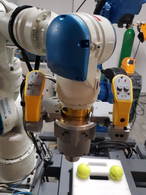
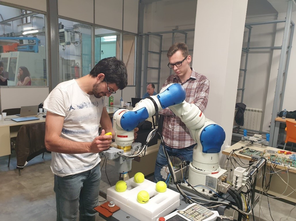
In the afternoon we were first introduced to the working principle of the haptic controllers on the robotic work-cell. Haptic controllers are comprised of load-cells, and load-cells are comprised by four strain gauges connected into the Wheatstone bridge. Controllers measure the force applied to them, and move the robot in the direction of said force.
By applying the force on controllers, load-cells deform elastically, so the resistance of strain gauges changes. For the Ohm law, when the resistance is for example increased, the output voltage is lowered, which then can be measured. Before performing the measurements, the device needs to be calibrated. The voltage level is then transformed into the applied force via microcontroller, which is later used by microcontroller to generate movement of the robot in specific direction.
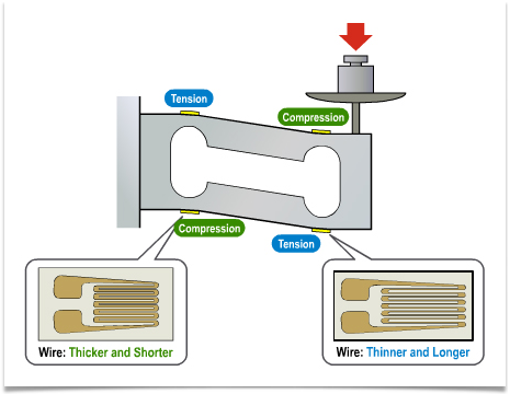
To be able to use the load-cell correctly, it is mandatory to calibrate it first. The behaviour of load-cell could be approximated as linear. Meaning that if we measure the voltage level for applied force of 1N, and then for 10N, we could draw a straight line on which it is clear to see correlation between applied force and output voltage. Said line can be represented as equation, which can be used by microcontroller to determine the force applied.
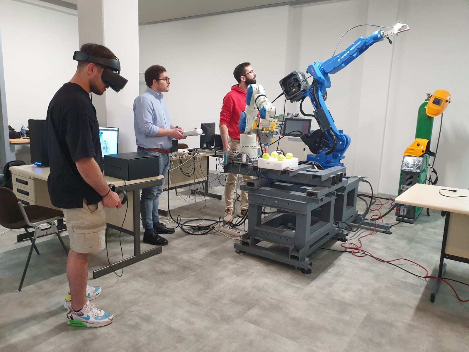
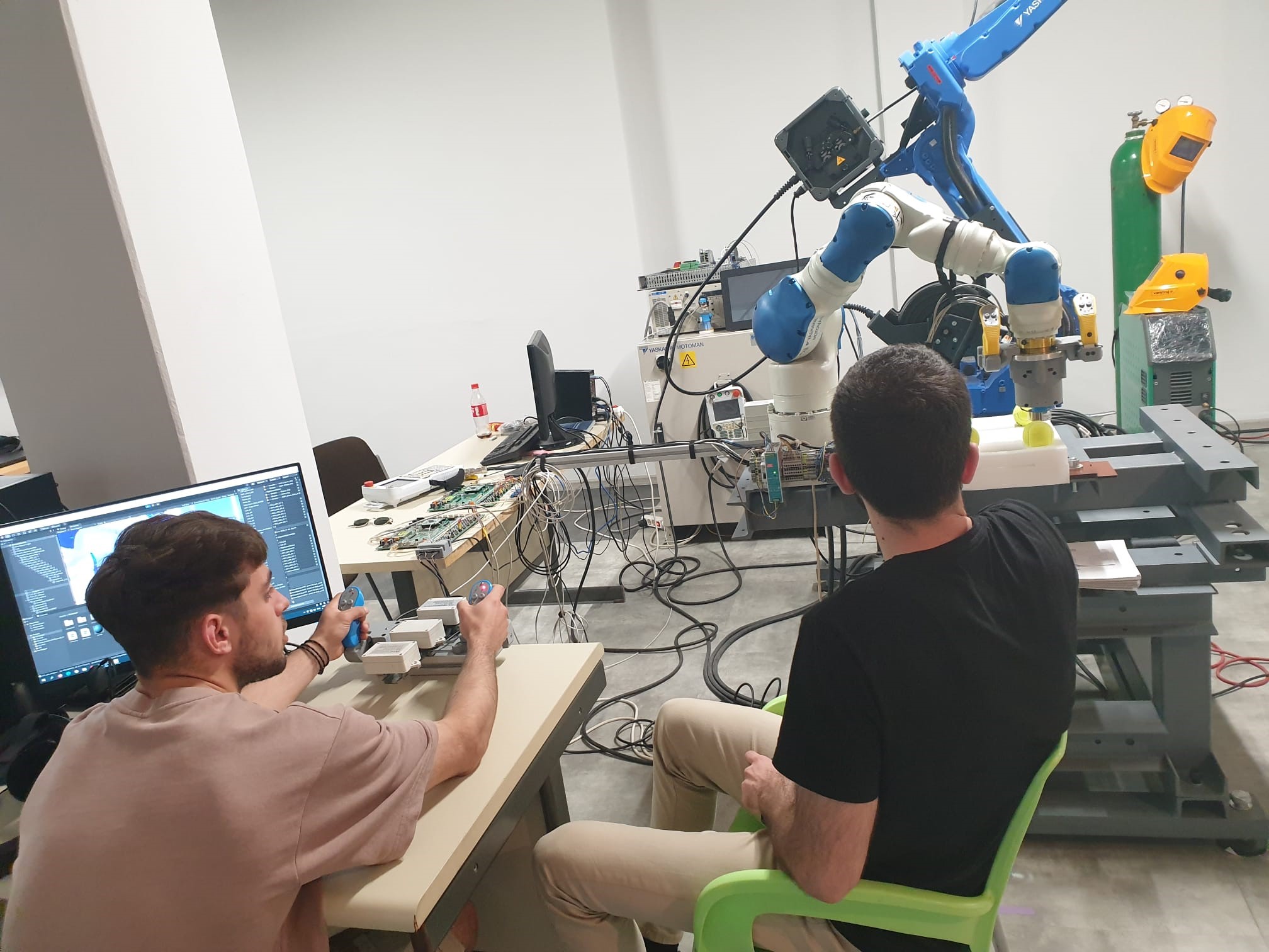
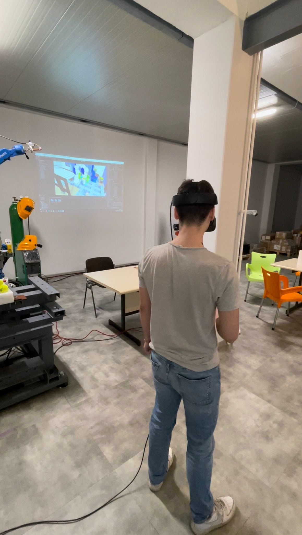
We tried operating the robotic work-cell, to get a feel for the controllers to prepare us for the lab on Thursday. When someone was operating the robotic work-cell, somebody else observing the digital shadow through Oculus headset.
There was also a demonstration of a physical shadow, which could be considered as inverse digital shadow. When the lecturer was moving the digital robot using the Oculus headset, the robotic work-cell functioned as a physical shadow.
DAY 4
Morning session
Objective: DIGITAL TWIN: step I - RWC Robot PbD using Digital Shadow
In the lab we operated the robot using Digital Twin configuration. We used the Oculus headset to see the robotic work-cell in VR, while also operating the physical and digital robot using the haptic controllers on the physical robotic work-cell. The task was to move the twin to touch the different balls in a pre-decided pattern using circular positioning, in the most effective way. The data from each operator was saved, and the intent is to combine the trajectories from each operator to a single trajectory.
Afternoon session
Objective: DIGITAL TWIN: Step II - RWC XR Robot PbD using full Digital Twin configuration
In the lab we operated the robot using Digital Twin configuration. We used the Oculus headset to see the robotic work-cell in VR, but the difference from the morning lab on day 4 is that the haptic controls used to operate the digital robot and physical robotic work-cell was not physically connected to the machine. They were instead external, connected to a microcontroller. The task was still to move the physical robot to touch the different balls in a pre-decided pattern using circular positioning, in the most effective way. The data from each operator was saved, and the intent is to combine the trajectories from each operator to a single trajectory.
DAY 5
Morning session
Objective: RWC DIGITAL TWIN XR Robot PbD using full Digital Twin
Different than the days before, the exercise fully revolved around moving the digital version of a robot, using VR controllers and VR vision. The assignment was, like before, to touch each of the balls shown in the workspace in a specific order. The movement was recorded so that data could be processed afterwards.
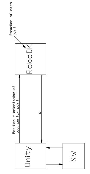
Information flow of digital model
The CAD-model is uploaded to SolidWorks, and the coordinate system of the parts are changed in order to function in Unity. The model is then uploaded to Unity as a GTLF-file, and in RoboDK downloaded from the online library. Unity sends the positions and orientation of the tool center points to RoboDK. RoboDK then uses this information to calculate the rotation of each joint, which is then sent back to unity. Unity also sends the updated information to SW. This is illustrated in the figure below.
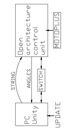
Information flow of robotic work-cell digital twin
In the figure below, the information flow between the pc, the OAC/FS100 and the robot is illustrated. When you add an update in unity, the pc then sends a string with commands to the OAC. The OAC then uses this information to move the physical shadow (robot). When the robot is controlled by an operator, information (comes from sensors) is sent to the OAC, which calculates the angles. This information is sent to the pc, and then used to move the virtual shadow in unity. When information flows in both directions as illustrated, we have a digital twin. The OAC and the pc is connected through a switch-device.
Notes on FS100 controller, Motoplus SDK and Oculus Rift S
Oculus Rift S
-
Key features:
- Uses LCD-screen with 80 Hz update sequence
- Resolution is 1200 x 1440 on each eye
- Integrated speakers with integrated microphone
-
5 integrated cameras and 6 degrees of freedom.
-
Benefits:
- Translates movements no matter what direction you look
- Controllers transport an array of gestures
- No external sensors needed
FS100/Yaskawa
-
Key features:
- Same brand as the robot MOTOMAN SIA 10F used in the JLL
- FS100 controller has an open architecture and communications
- Powerful controller for high/performance applications
- Compliant to safety standards
- It allows you to control the robot using a teach pendant
- Designed for packaging, small parts handling and assembly applications
- Designed for Motoman® robots with payloads of 20 kg and under
- High-speed I/O response and high-resolution timers
- Supports a wide range of communication networks
- Single controller supports up to eight axes
- There is a Dual Robot Control option
- It can handle up to 6 concurrent jobs and 1 system job
- It has 16 inputs and 16 outputs
- It allows you to control the robot using a teach pendant.
- It can handle up to 6 concurrent jobs, 1 system job
-
It has 16 inputs and 16 outputs
-
Key benefits:
- It is small and compact
MOTOPLUS SDK/Yaskawa
Key features of the software MotoPlus SDK / Yaskawa:
- Same brand as the MOTOMAN SIA 10F and FS100 / Yaskawa used in the JLL
- Is a software development kit for specialized control and monitoring applications for robot systems
- Set of programming tools for developing custom application tasks to run directly on the robot controller concurrently with the standard software
- Comprehensive set of Application Programming Interfaces (APIs)
- Development is done in C-programming languages for minimal overhead
- Plug-in for Microsoft Visual Studio
- Enables development of applications for integration with nearly any device
-
Allows development to be done offline using a standard Windows PC
-
Key benefits:
- Provides real-time access and communications with the controller
- Enables interaction with any computing device
- Can be used to embed complex algorithms for data acquisition in an ANSI C programming environment
- Comprehensive API allows access to control and monitor many robot functions through Ethernet socket or interface
- No additional hardware or costly development tools are required.