A2.2 - Behavior Development
The development of robotic behaviors is implemented using third-party software called Robot Operation System (ROS), a well-known framework for creating robotic software that uses a collection of tools, libraries, and conventions intended to simplify the process of creating complex and robust robotic behaviors on a wide variety of robots.
To simulate any robot in ROS it is necessary to have the Unified Robot Description Format (URDF) file of the robot. The URDF files consists of an XML format for representing and describing a robot model while taking into account the mating information between joints and physical properties (inertia, mass, etc).
Depending on the robot there may be two scenarios, one in which the manufacturer delivers those files, and the other in which they do not deliver them, so they must be built on their own:
Building a URDF file from Solidworks
The example of a Universal Robot UR5e is reported. A digital model, in neutral, .stp format, is available for download in the documentation area of the Universal Robots website.
Once ready, the model can be imported in Solidworks, where it should appear as completely fixed without possibility of relative movement between its subcomponents. A series of operations is then needed to realistically represent the relative movement between the links of each arm according to the degrees of freedom of the actual cobot of reference:
- Select the first component on the feature manager (the father of all the other components), then right-click and select the “Dissolve Feature” command.
- Save the model as an assembly (.SLDASM format). This allows to make changes and manipulate the geomentric properties of the model.
- On the feature manager, it is convenient to re-arrange the hierarchy and to re-name the components according to the robotics standards, as shown in the related image. In order to establish parent/child relationships between subparts, the “Form New Subassembly” function must be used.
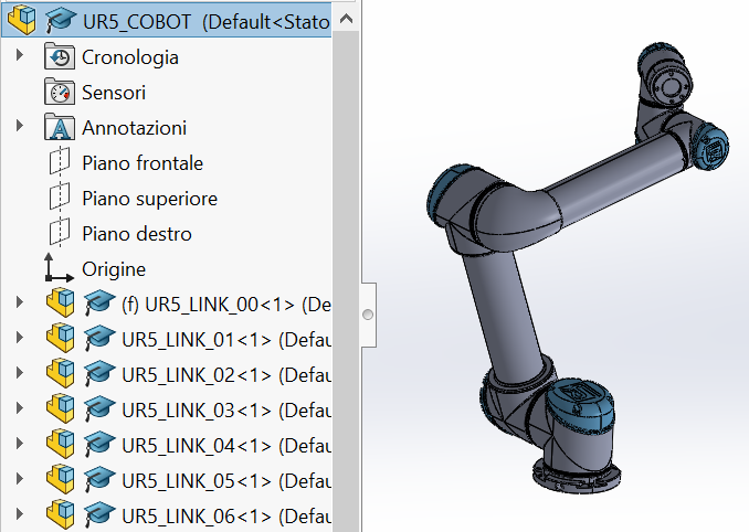
Geometric Model in Solidworks
- At this point, all the links must be set as floating (“Float” setting), except for the base one (UR5_LINK_00), that should be kept fixed (“Fix” setting) to the ground.
- It is then necessary to define the mates (tangent surfaces/coaxial surfaces) to allow the relative movements between each link.
- Creating an exploded view and, possibly, an animation is recommended to highlight the different parts that compose the cobot and how they’re joint.
- Finally, an adequate end-effector has to be chosen in relation to the task that the cobot will virtually perform. A gripper model, called 2FG7 by OnRobot is presented hereby.
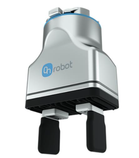
Gripper Model
- After downloading the .stp file, this was opened on SolidWorks, repeating the steps performed for the general cobot model to enable the relative movement of the gripping components (i.e., horizontal translation). It was then integrated to the cobot assembly.
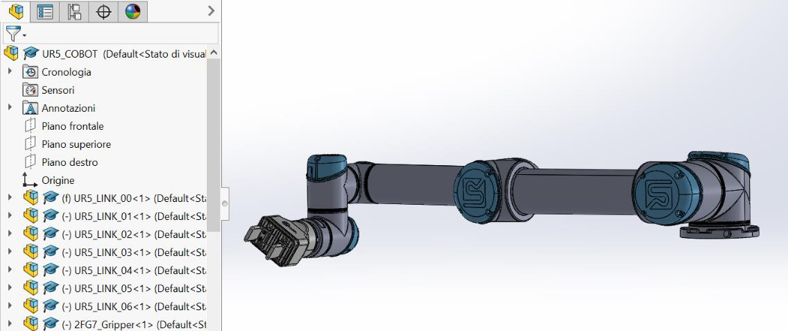
Assembly of Gripper Model and Cobot in Solidworks
A direct kinematic model is the starting point to correctly set up the behaviour of each component of the cobot. It consists in determining the position and orientation - namely, the posture - of the end effector of the cobot in terms of joint variables. In the following procedure, a methodology to connect the Kinematic model to Solidworks is documented in order to test if the various parameters are correctly set up.
The documentation provided on the UR website about the Denavit-Hartenberg convention can be used in order to study the direct kinematic model of the cobot, as shown at this link. The Denavit-Hartenberg model is one of the best known and widely adopted models for the description of the kinematics of automated manipulators in a standardized way. It requires the attachment of a coordinate reference frame to each joint to define the four DH parameters -link length, link twist, link offset and joint angle-, as shown in the following figure with reference to a generic UR cobot.
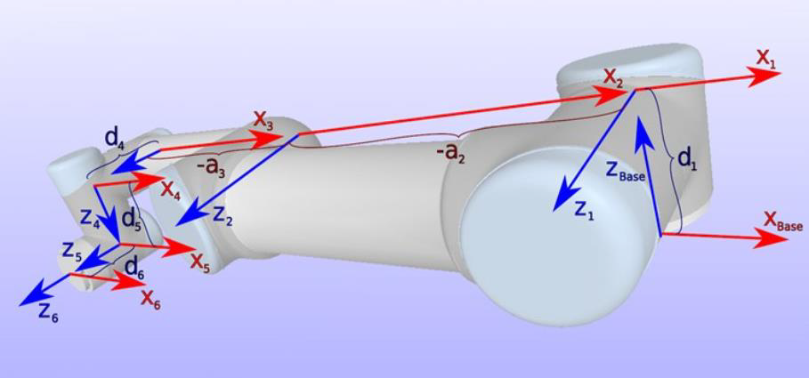
Denavit Hartenberg representation on Cobot
With reference to the image above, two of the four DH parameters are visible:
- parameter ai, which is the distance between zi axis and zi-1 axis, thus defining the link length;
- parameter di, which is the link offset of the xi axis from the xi-1 axis, measured along the zi-1 axis. The other two parameters are angular:
- parameter ϑ𝑖, which is the angle about the zi-1 axis between xi axis and xi-1 axis;
- parameter α𝑖, that is the angle about common normal between zi-1 axis and zi axis. While the other parameters are constant, parameter ϑ𝑖 represents the real variable of the kinematic study.
By following the scheme of the DH parameters provided in the UR documentation, the local reference systems of each joint have been set in SolidWorks as shown in the figure below.
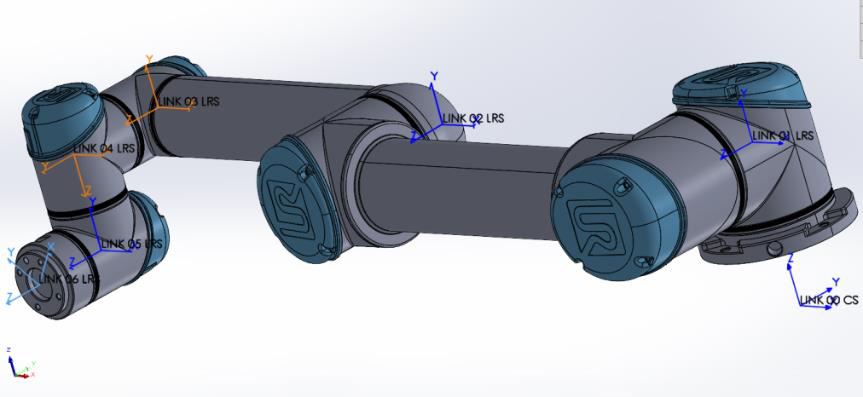
Denavit Hartenberg representation in Solidworks
A recommended step to verify the correct application of mates between links is the simulation of the direct kinematic model by means of an Excel tool provided by Universal Robots.
According to the DH model, the generic transformation matrix between two consecutive links (𝑖−1,𝑖) can be defined as follows:
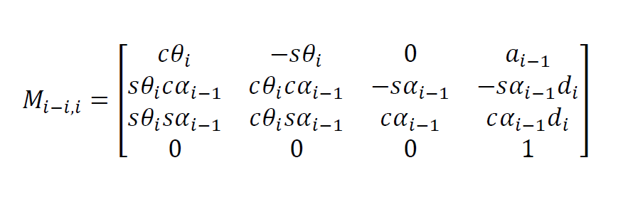
Transformation Matrix
The multiplication between all the matrices, defined for each couple of consecutive links, allows to compute the coordinates of each joint, thus defining the final configuration of the cobot in the space.
Exporting a URDF file from Solidworks
The URDF exporter allows to export, in a few steps, Solidworks Parts and Assemblies into a URDF package. For doing so, after having installed the plug-in, a new tree hierarchy must be created, where the base link is set as the parent of link1, link1 as the parent of link2 and so forth.
For each link, it is possible to specify the type of joint, that for the cobot are all revolute type, and the related reference systems. Instead, for the body of the gripper a fixed joint is applied, whereas the two fingers are specified as prismatic joints.
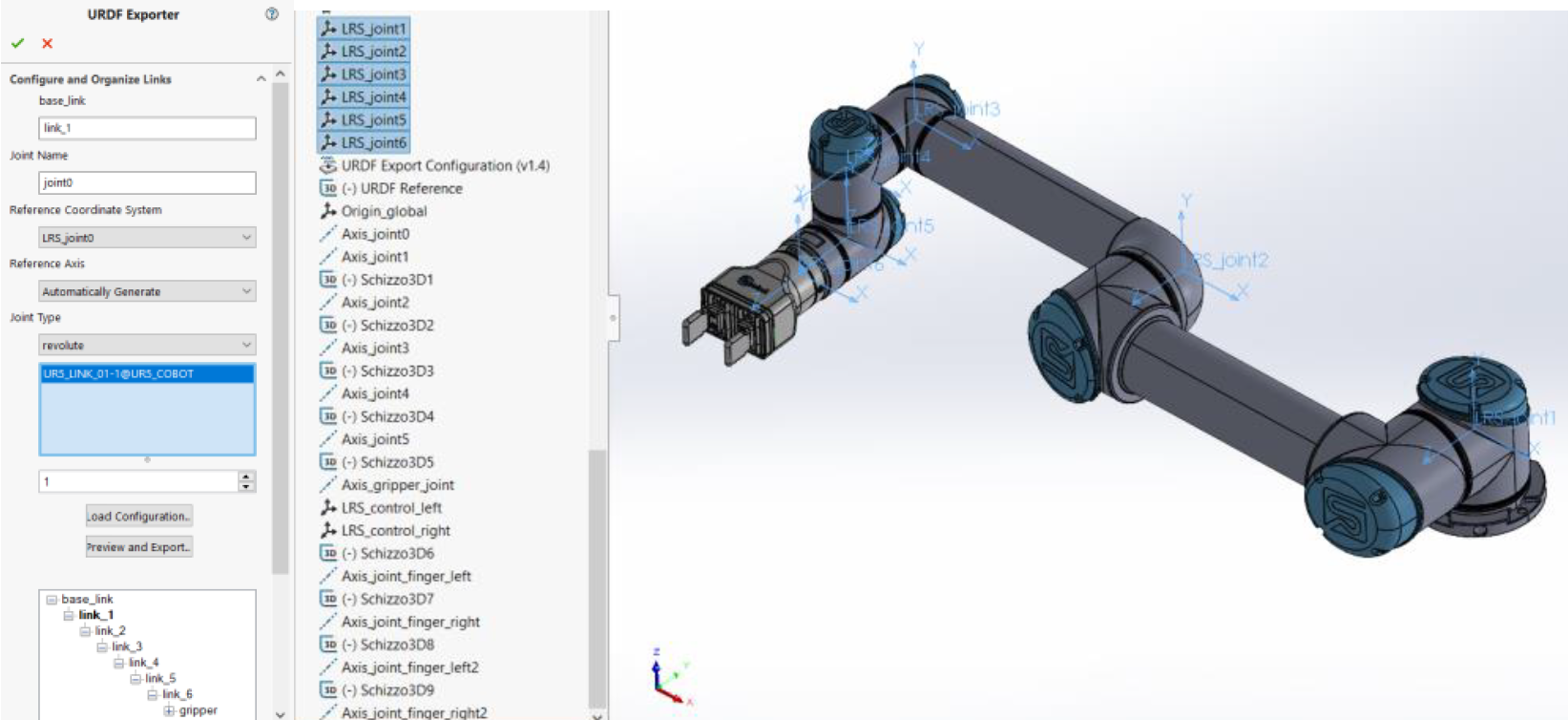
Exporting a URDF file from Solidworks
Once the setup procedure for the generation of the URDF package is complete, it is possible to move on by exporting the files to a new folder. By using the plug-in mentioned in these guidelines, the process in broadly automatic, and a new directory is created to a specified position in order to include all the necessary data. In this way the exporter creates a ROS-like package that contains a directory for meshes, textures and additional information including the URDF file itself.
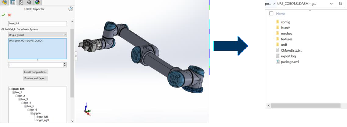
URDF Package
Importing the package in ROS
A powerful ROS tool is Moveit, which enables motion planning, manipulation, 3D perception, kinematics, control and navigation of the robot.
Start by creating the ROS workspace, once created, import the URDF file into the src folder. Use ROS launch to launch moveit_setup_assistant. It is a graphical user interface for configuring any robot for use with MoveIt.
When the assistant finishes the setup, the robot can be visualized via RViz on a virtual environment (scene) and is now ready to create start and goal states for the robot interactively, test various motion planners, and visualize the output.
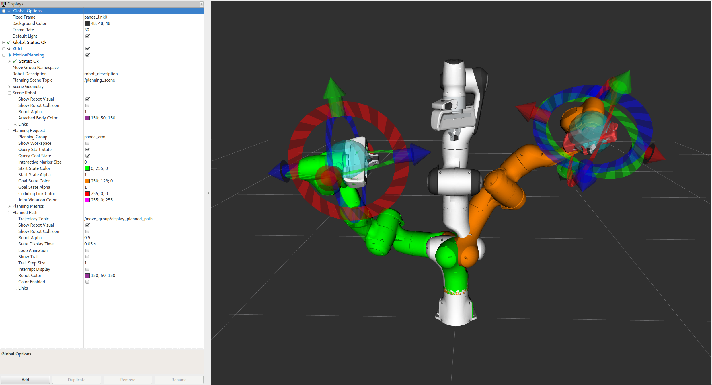
Robot from URDF package in Moveit
Creating a pick and place task
To perform a Pick and Place scenario, it is necessary to create and run a script, ROS supports scripting in both Python and C++. Here are the main functions to be implemented, one examples is available here.
-
AddCollisionObjects
Add and place the objects which are part of the scene as well as the target, the object to be picked up. So when the trajecotory is computed it will avoid collisions with the objects that have been added. -
Pick
The pick task is divided into the following subtasks, grasp pose, pre-grasp approach, post-grasp retreat, for each of them define the pose (position and rotation) of the hand, in relation to the base frame and the position of the target. -
Open/Close Gripper
Assign the robot fingers and set the opening and closing positions. -
Place
The pick task is divided into the following subtasks, place location pose, pre-place approach, post-grasp retreat, or each of them define the pose (position and rotation) of the hand, in relation to the base frame and the place position.
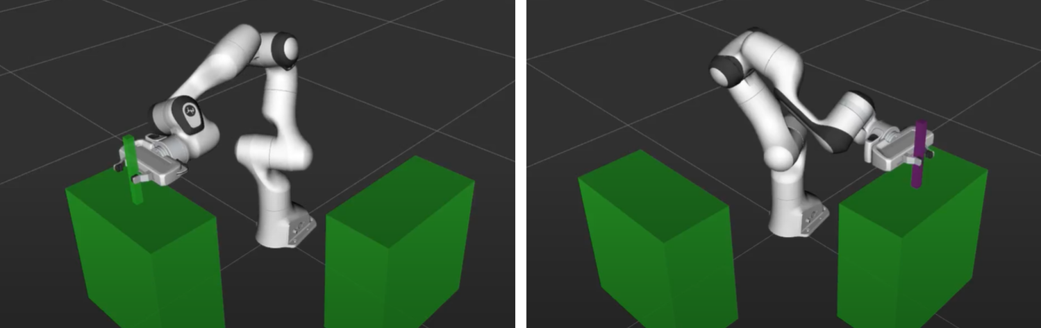
Execution of Pick and Place task in Moveit
Input
CAD models of the system ( i.e. robot) as well as the physical properties of the system such as inertia, mass, etc. Definition of the relationship between the components and subcomponents. Documentation and other elements related to the system.
Output
- Geometric model in Solidworks representing the relative motion between the robot links.
- Direct kinematic model detailing the end effector pose in terms of joint variables.
- Exported URDF package containing all necessary data including meshes, textures and the URDF file itself.
- Robot fully setup in the ROS using MoveIt, ready for motion planning and other tasks.
- Pick and Place task script for ROS to execute specific robotic tasks.
Control
The accuracy of the CAD models, together with the proper implementation and adjustment of the robot kinematics, to ensure a realistic representation of the robot’s behavior. Furthermore, accuracy is crucial when employing efficient motion planning and navigation using MoveIt in ROS.
Resources
- SolidWorks CAD software
- URDF exporter plugin for Solidwork
- Robot Operation System (ROS)
- MoveIt toolkit in ROS for motion planning and navigation.