A2 - Simulation
Creating an effective simulation for integration into a digital twin is a multidisciplinary process that integrates real-world data and advanced simulation modeles. This process serves to create a digital shadow of a physical system, providing information for predictive analysis, system optimization and potential failure detection.
By defining and developing accurate system behavior based on actual real-world data, simulation captures the essence of the real system. This accuracy ensures that the digital shadow can faithfully reproduce the system’s responses under various conditions, and the integration of the behavior into a 3D structure brings a visual dimension to the simulation allowing a more intuitive understanding of the system behavior. Finally, calibration and adjustment closely align the digital shadow with the real-world system. The result is a powerful digital tool that mirrors the behaviors of the real-world system.
Structure of the workflow
| CONTROLS: Technical specification - Mathematical validation - Third-party software simulation - Data integration protocol | ||
| INPUTS: Real system and its 3D representation | 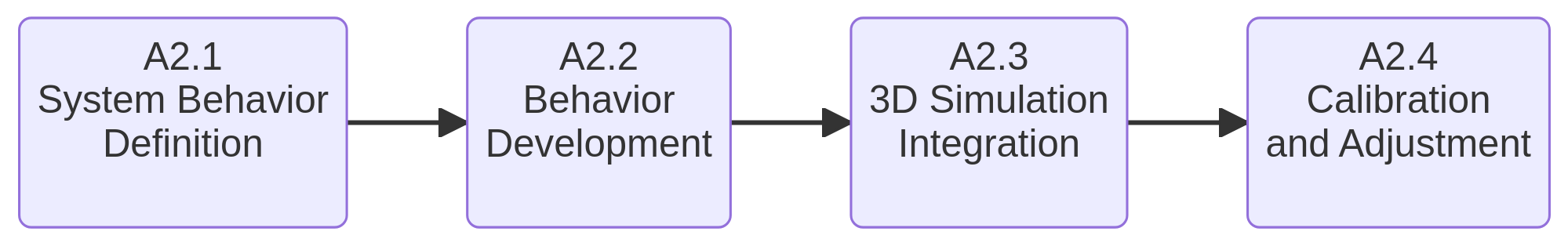 | OUTPUTS: Digital Shadow |
| RESOURCES: Simulation and visualization software - Historical records and real-time metrics |
Simulation workflow
Workflow Building-Blocks
| Activities | Guidelines |
|---|---|
| A2.1 System Behavior Definition | • Description: To define the behavior of a system, it is necessary to carry out an exhaustive study of the system and its environment. For this, it is crucial to identify the main internal and external variables that influence and impact the behavior to be simulated. These variables may include factors such as speed, temperature, pressure among others. In addition, it is critical to collect all the necessary data, including historical records and real-time metrics, to facilitate the simulation process. Sometimes it may be necessary to implement specific hardware to collect data from the system. • Input: Real System • Output: Specific variables that impact system behavior, historical records and real-time metrics. • Control: The technical specifications or parameters that are used to guide and regulate the simulation process. • Resource: Technical data sheet and instrument of analysis and measurement. |
| A2.2 Behavior Development | • Description: Accuracy in the behavior of the system during simulation is vital. This accuracy is necessary because, when the virtual model interacts with the real system -either sending or receiving information-, the response is expected to be identical on both virtual-real sides. There are two possible alternatives for developing the system behavior: a) Development of a particular custom behavior: this can be achieved by defining own behavioral equations from the parameters and data collected. An example would be the algorithms for calculating the inverse kinematics of a robot. It should be noted that this is a task that requires solid mathematical knowledge. b) Delegate the behavior to a third party: A specialized software can take control of the behavior to be simulated by entering the parameters or information that has been collected, such as a robotic simulation software like RoboDK. However, this involves creating a connection between the rendering software and the simulation software, which could cause latency problems. Both cases are valid and depend only on the purpose of the simulation. • Input: Specific variables that impact system behavior and historical records and real-time metrics. • Output: Custom behavioral model or third-party software integration • Control: Mathematical validation, third-party software validation, expert and peer review. • Resource: Technical specifications of the system, scientific literature, software documentation. |
| A2.3 3D Simulation Integration | • Description: Once the system behavior has been developed, the simulation data must be integrated into the virtual representation of the system, i.e. the 3D models. For this, the following two tasks must be performed: a) 3D Structuring: This process consists of taking the visual representation of the system and recognizing its main components, which may include axes, joints, links, etc. These components should be in a hierarchical structure based on how they are linked to each other and how they move relative to each other. The positional relationships and movement constraints between each component must be clearly defined. In addition, it is necessary to eliminate any superfluous or redundant elements, such as bolts and nuts, that do not directly contribute to the simulation. b) Data Integration: This stage involves the development of components or the writing of code that will be responsible for incorporating the simulation data (dynamic, kinematic, thermal, electrical, and others) into the visual elements of the system. This process must be carried out in a way that accurately reflects the limitations and constraints of each system element. These tasks are essential to ensure that the 3D models that are part of the system accurately and effectively reflect the simulation results that will in turn reflect the behavior of the real system. • Input: 3D model of the system and simulated behavioral data. • Output: 3D visualization of the result obtained from simulated behavior. • Control: Data integration protocol, design guidelines and software parameters. • Resource: Software tools for 3D modeling and simulation. |
| A2.4 Calibration and Adjustment | • Description: After the behavior has been simulated and integrated into the 3D model, it’s necessary to calibrate and adjust the system to align with the real-world system as closely as possible. Calibration consists of aligning the behavior and response of the simulated system with the real system. Adjustment may include modifying parameters, altering certain behaviors, or modifying the 3D structure to ensure that the simulation accurately represents the real-world system. It is also possible to compare the output data from the simulation and the output data from the real system. This activity is an iterative process, in order to match as closely as possible the behavior of the real system. • Input: 3D visualization of the result obtained from simulated behavior and Real world data. • Output: 3D visualization of the calibrated and adjusted simulation that accurately represents the real-world system. • Control: Real world system data and performance benchmarks. • Resource: Real world performance data, experts for verification and adjustment, simulation software for model |