A1.3 - Digital Human - Avatar
Avatars in virtual environments can vary in terms of their fidelity, or how closely they resemble and behave like a real human. The most common types of avatars are:
- Complete avatars:
These avatars include a representation of the head, hands, feet, and pelvis. They may use inverse kinematics algorithms to compute the positions of the extremities based on data from controllers and headsets, or they may use external hardware to track the user’s body and inject this data into the avatar. This allows the avatar to move and behave in a way that is similar to the user’s own movements and actions. - Head-and-extremities avatars:
These avatars include a representation of the head and hands, and they use data from controllers and headsets to accurately position a 3D representation of the avatar’s hands and head in the virtual environment. - No-avatar:
In these virtual environments, the user does not have a representation of their body. Instead, there may be a 3D visualization of the controllers or an entity that represents the user. This allows the user to interact with the virtual environment, but they do not have a physical body within it.
Below we describe the main steps to have a complete representation of the user in a virtual environment using an avatar which is fed by the data acquired by an external hardware.
Avatar Modeling
The first step in creating a 3D avatar model is conceptualization and design. Depending on the virtual environment where it will be used, for example, on a space station, it should look like an astronaut, rather than a construction worker. This conceptual sketch forms the basis of the 3D modeling process.
For the modeling phase, software such as Blender, Maya or ZBrush are often used. The initial sketch is transformed into a 3D model using various tools and techniques of these programs, such as sculpting, extruding and retopologizing. It is important to focus on details that increase realism, such as correct anatomical proportions and articulation of joints.
Once the basic 3D model is created, the next phase is texturing and shading. This process imparts color, material attributes and textures to the model, giving it a realistic appearance.
The last step is rigging, in which a digital skeleton is created for the model. Each bone in the rig corresponds to a part of the 3D model, allowing it to move along with the user’s actions during motion capture sessions.
The 3D avatar model can be exported in a format compatible with the XR development platform of choice, such as Unity or Unreal Engine, ready for integration with the motion capture data.
Setting Up Capture Area
Installing a motion capture system requires careful space preparation, camera placement and calibration. This involves creating a safe area, controlling light sources and reducing reflective surfaces in the area. The cameras are then strategically placed at high points with clear lines of sight. Calibration concludes the process, establishing a clear and accurate reference point within the capture area.
The motion capture system is composed of eight OptiTrack Flex 13 volumetric capture cameras that are controlled by Motive software on a Windows computer.
To properly set up the capture volume, it is necessary to first remove any unnecessary objects from the area and block sunlight if possible. It is good practice to minimize the presence of highly reflective surfaces, as they can cause interference in the data. If possible, it is advisable to cover the floor with a black matte material.
In order to mount the cameras, they should generally be placed at high positions, around the edge of the capture volume, at varying heights, and with unobstructed views. In order to achieve accurate and stable tracking data, it is crucial that all cameras are properly focused on the target volume.
To calibrate the system, the volume should be calibrated by moving the calibration rod through the entire area at various points and angles. After completing this process, the ground plane should be set to define the global origin.
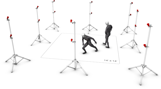
Illustration of a capture area
Skeleton Creation and Markers Placement
In a motion capture system, rigid bodies and skeletons are tracked with specialized equipment and marker placement. Rigid bodies are set up by attaching markers to any object for tracking. Skeletons, require users to wear specific motion capture suits.
The optitrack system supports tracking of both rigid bodies and single or multiple skeletons.
To track the skeleton the user will suit the following mocap:
- Optitrack Motion Capture Suit (size adult Large)
- Mocap Foot Wrap (large)
- Mocap Glove Large/X-Large
- Marker w/ X-Base: 9mm and 14mm
-
Motion capture Hand/ Finger Markers
- To set up rigid bodies
Attach either passive or active markers to any object that you would like to track. To attach passive markers, use marker posts and adhesives or velcro. Allow some space between neighboring markers for optimal tracking. When all of the markers are visible in the viewport, select the markers by dragging a box around them. Right-click near the selection and choose “Create Rigid Body”.
- To set up skeleton
Open the Builder pane and select the skeleton that you would like to track. The Builder pane provides a 3D model showing all of the marker locations needed to track a particular skeleton.
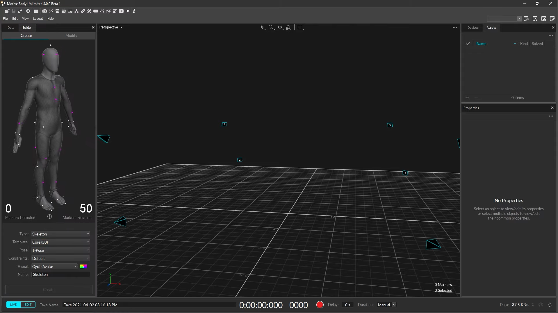
Motive’s main window
With the subject in their Mocap suit, start placing markers as displayed in the Builder pane. When placing markers near joints, ask the subject to bend their elbows and knees to guide the placement on the boney parts of the joint for the best tracking results. Ask the subject to stand in a T-Pose, with feet shoulder-width apart, toes pointing forward, arms stretched to the sides shoulder height, and palms facing down forming a ‘T’ shape. Drag a box around all of the markers, and hit create.
A skeleton avatar should instantly appear, confirming tracking in Motive.
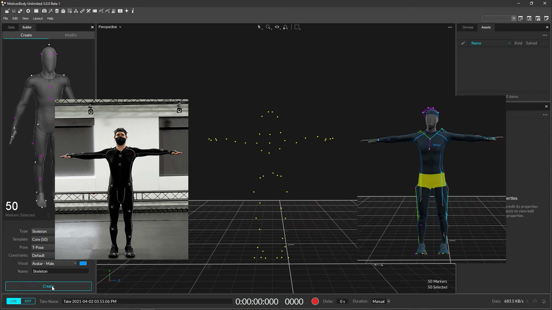
T pose tracked by Motive
Data Streaming
Many motion capture software solutions provide options to transmit tracking data to external applications, such as game engines, in real-time.
The data can be streamed from live captures or from previously recorded data. These streaming settings are typically adjustable within the software interface. Certain protocols might need to be enabled, and correct network configurations, such as IP addresses, are necessary to ensure successful data streaming.
Motive offers a plugin to stream tracking data to applications in real time, this plugin is supported by Unity or Unreal Engine or can be created from scratch from your custom library. The tracking data can be streamed in real-time either from a live capture (Live Mode) or recorded data (Edit Mode). The streaming settings are configured by modifying the Streaming Settings. NatNet streaming must enabled and the correct IP address must be set.
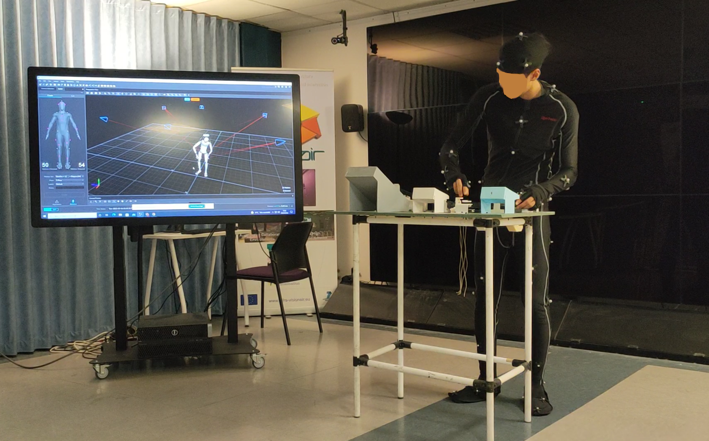
In-house tracking of a full body while performing an assembly task in order to analyz ergonomics
Data Integration
The OptiTrack Unity Plugin allows you to stream real-time Rigid Body, Skeleton, and HMD tracking data from Motive into Unity. Using the streamed data, objects and characters in the scene can be animated.Using a simple server-client structure, where motive is the server and unity is the client.
By integrating with Unity’s animation system, Mecanim, the Unity plugin allows Motive to stream full body Skeleton data. The Skeleton tracking data from Motive is streamed out as hierarchical bone segment orientations, and this data is fed into the Unity’s Mecanim system which allows animating characters with different proportions.
Unity Version: It is highly recommended to use 2020.3+ LTS version.
- Import the unity package
- In a new scene create an empty object and add the script
OptitrackStreamingClient.csreferencing all fields according to the Motive configuration - To animate a rigid body add the script
OpitrackRigidBody.csset the StreamingClient and it is important to set the correct rigid body ID found in Motive. - To animate a skeleton add the script
OptitrackSkeletonAnimator.csEnter Skeleton Asset Name which is assigned in Motive and the unity avatar that controls the 3D model of the avatar. Inside the plugin comes an avatar, but you can also use custom avatars.
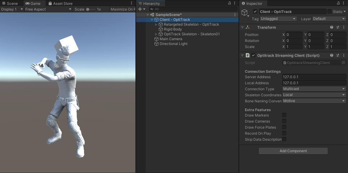
Full body avatar rendering in Unity
Input
User movements to be tracked in real time and integrate them into a virtual environment to ensure an accurate virtual embodiment of the user.
Output
Avatar which embodies the user in a virtual environment, creating a real-time representation of the user’s motion in a virtual envirioment.
Control
- Fidelity of the 3D model/Avatar representing the user
- Accuracy and latency of user tracking.
Resources
- Motion capture equipment: The cameras and motion capture suits used to collect user data.
- Motion capture suit and markers: Special clothing and markers to be worn by the user during capture.
- 3D modeling software (Blender, Maya, ZBrush): Used to create the 3D avatar model.
- Motion capture software (Motive): Used to capture and process the user’s movements.
- Application development software (Unity, Unreal Engine): Used to integrate the motion capture data with the avatar in the virtual enviroment.