A4.2 - Use Case Model
In VR and AR application the lowest level actions are selection, navigation and manipulation :
-
Selection allows to specify which objects in the scene is currently undertaken. It may lead to change the behavior of an action or propose some context actions often presented as context menus.
-
Navigation allows to change the point of view on the model. In 3D navigation is understood as a physical motion of the observation camera but it can be also some buttons or actions to switch from one panel to another one in 2D contexts.
-
Manipulation allows to change the position and orientation of objects in the scene.
The metaphors for selection, navigation or manipulation depends on the technologies capacities and choices made by the developer team. For example navigation may be operated as a flyer mode or through teleportation. Some ideas about the expected metaphor are suggested by the storyboard but the use case model does not describe this level of detail.
The use case mode explains how the main end-user functions request sub-functions. The functions are recursively described until the low level that should be selection, navigation and manipulation.
In the above example the use case explains a single use case (Associate virtual and physical models). To enable this function, he must open the camera, load a model, and create pairs of points. All these operations does not need nor navigation or manipulation but selection. But we highligth 4 types of selections which will be developed separately. If the user interface is limited to this single use case then there is no much added value. Whenever the basic use cases are shared by several upper use-cases then this work highlights the basic functions to ne developed once and reused in various contexts.
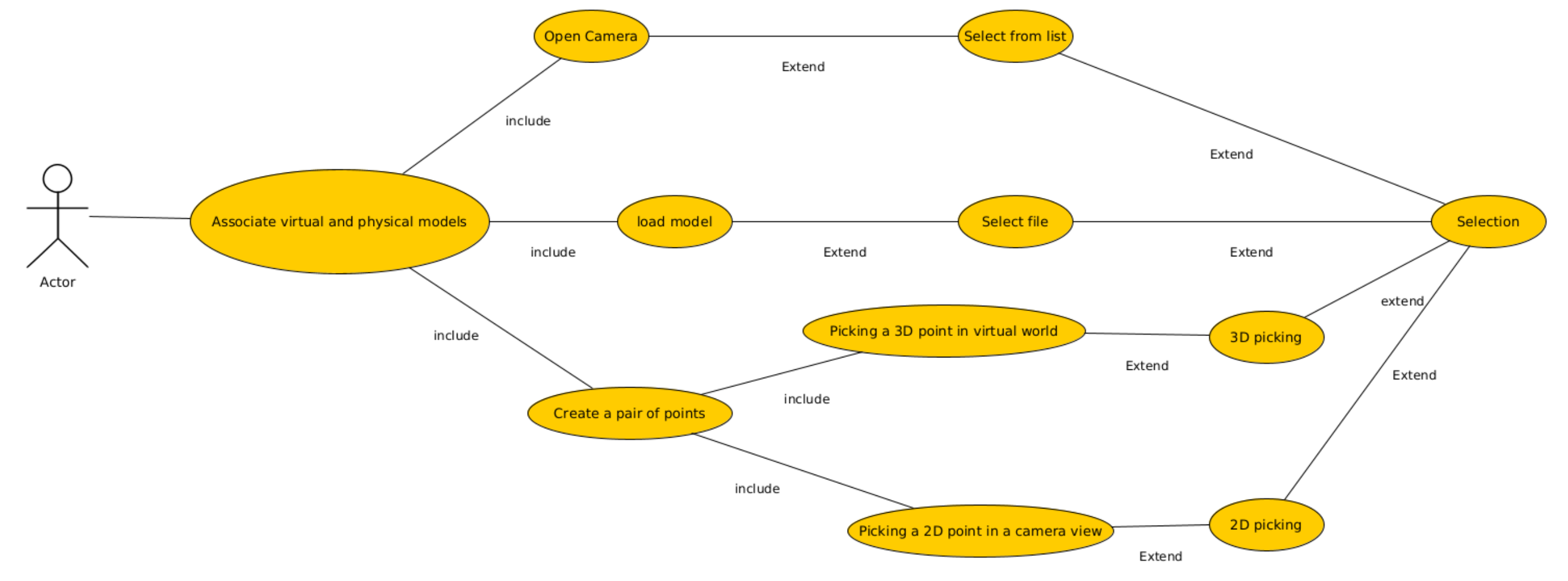
Associate virtual and physical models example
Input
The scene actors are the main input to draft the use case. They are the external entry point of the use case and the message between single use case (function and actors) describes the information flows
Output
The output is mainly represented is a use case graph (In the picture, here a UML use case diagram is used). But indeed the real output is a hierarchy of functions from high level ones to very basic ones. By converging on selection, navigation and manipulation functions we ensure that a VR/AR environment can be developed based on this specification.
Control
It is never obvious to fix the level of detail and to stop expanding such a model with new functions. The initial specification (the storyboard indeed) is a reference to decide when we have enough details and when the use case is complete enough.
Resource
There are plenty solutions to describe the model but we promote to use the well known and practiced UML use case diagram. A use cas diagram mainly contains actors :
| Symbol | Function |
 | Representation of humans or system acting on the user interface |
 | The use case diagram is made of many use cases. A use case is a function of the user interface |
 | The extend link which defines that a use case generalizes another use case. |
 | The include link which identifies that a use case need sub use cases to be performed. |
UML use case diagram
Many tools are dedicated to create UML Graph. Here the software yEld was used.